
An energy monitoring and management system based on an energy storage device and its management method

A monitoring management and energy storage device technology, applied in the field of energy Internet, can solve the problems of not solving energy storage battery system integration and energy management, and not solving the problem of energy storage battery operation optimization management and control, so as to improve energy utilization efficiency and improve social Economic benefits and the effect of improving the level of system operation and management

Active Publication Date: 2022-04-12
方日升 +1
View PDF15 Cites 0 Cited by
  • Summary
  • Abstract
  • Description
  • Claims
  • Application Information

AI Technical Summary

Problems solved by technology

[0003] The present invention relates to energy storage system integration technology and energy management technology. The prior art does not solve the problem of optimal management and control of the operation of energy storage batteries and electrical equipment during the entire life cycle, and does not solve the problem of system integration and energy storage batteries in large-scale applications. Energy management issues; in view of the deficiencies in the prior art, the present invention provides an energy monitoring and management system based on energy storage devices and its management method, the purpose of which is to give full play to the role of energy storage batteries and improve the flexibility, safety, and Stability, improve the level of renewable energy consumption, improve the energy utilization efficiency on the user side, better meet the power demand on the user side, and help to improve social and economic benefits and environmental friendliness as a whole

Method used


Image

  • An energy monitoring and management system based on an energy storage device and its management method
  • An energy monitoring and management system based on an energy storage device and its management method
  • An energy monitoring and management system based on an energy storage device and its management method

Examples


Embodiment 1

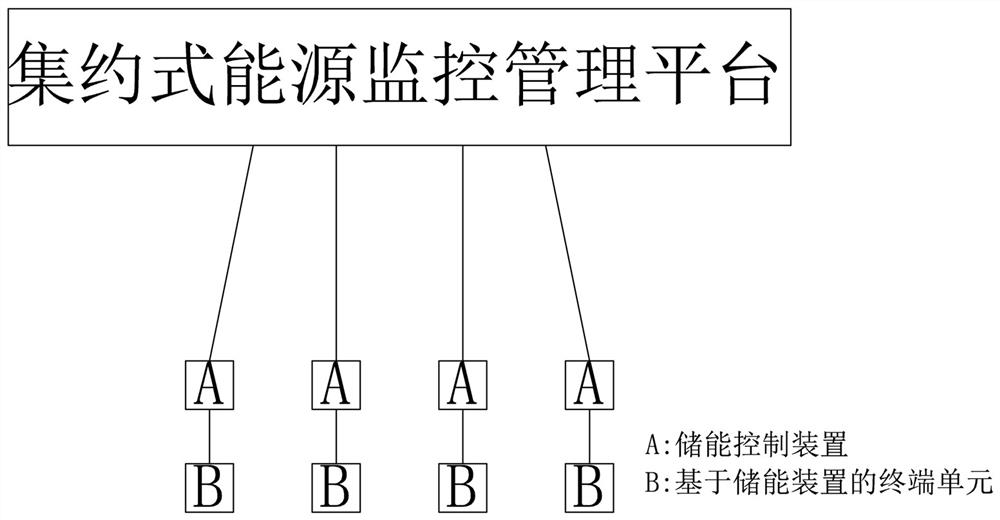
[0107] Such as image 3 As shown, a pair of application deployment modes of an energy monitoring management system based on the energy storage device is provided by the energy storage device, which is the simplest application deployment mode, energy control device, and a terminal unit based on the energy storage device. You can be installed on the same location or mounted at different locations.

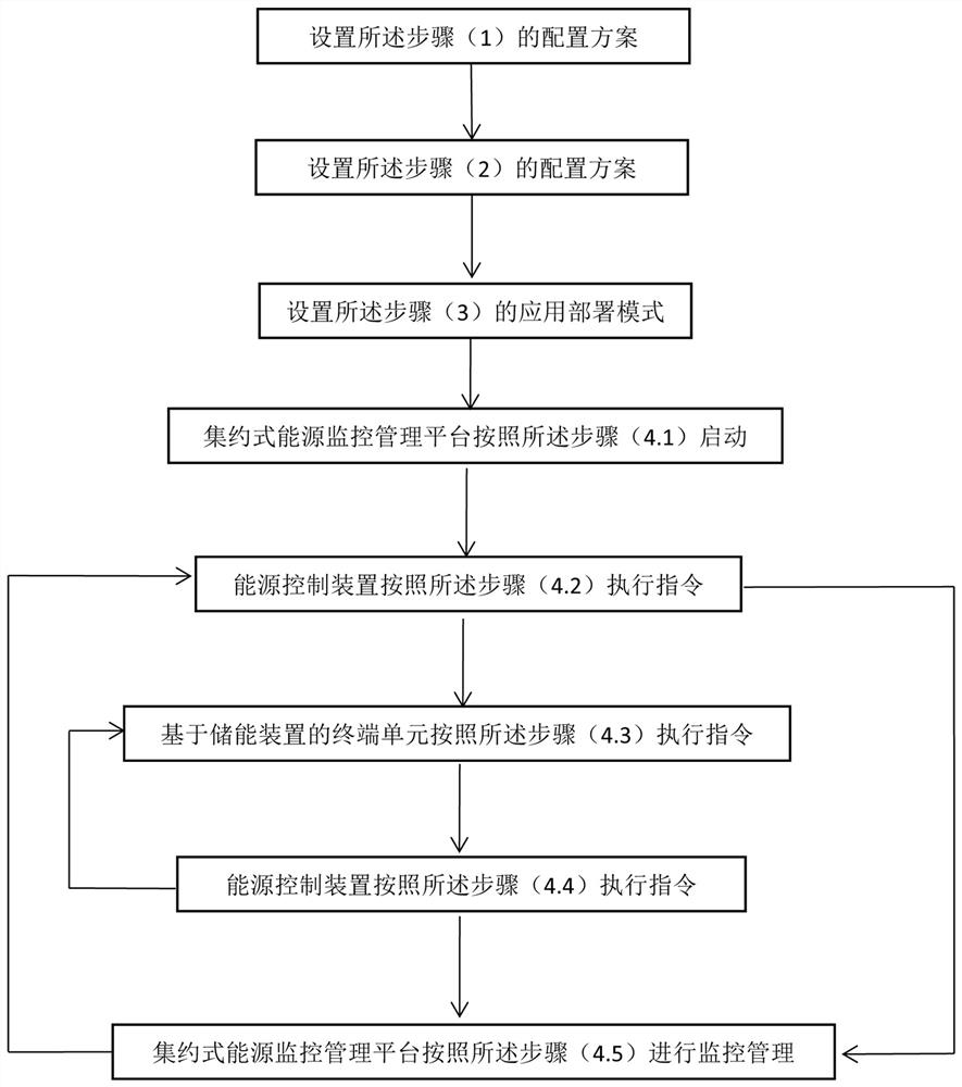
[0108] Such as figure 2 As shown, the energy monitoring management method based on the energy storage device, in one-to-one application deployment mode, includes the following steps:

[0109] (1) Set the configuration scheme of the terminal unit based on the energy storage device, including the economic operating mode selection based on the terminal unit of the energy storage device, the battery and the electrical energy matching of the electrical energy, and the number of terminal units;

[0110] (2) Set the configuration scheme of the energy control device, that is, the number of energy...

Embodiment 2

[0121] Such as Figure 4 As shown, this example provides a pair of multi-application deployment modes, simple structure, and each energy control device, which is simple, and each energy control device is connected, and each energy control device is connected. The terminal unit based on the energy storage device can be mounted in the same place, or may be mounted different locations, and the electrical device can be different in the terminal unit of the energy storage device, and the corresponding battery type and capacity can also be different.

[0122] Such as figure 2 As shown, the energy monitoring management method based on the energy storage device includes the following steps in a pair of multi-application deployments:

[0123] (1) Set the configuration scheme of the terminal unit based on the energy storage device, including the economic operating mode selection based on the terminal unit of the energy storage device, the battery and the electrical energy matching of the ele...

Embodiment 3

[0135] Such as Figure 5 As shown, this example provides a multi-pair multi-application deployment mode of the energy monitoring management system based on the energy storage device, and each plurality of energy control devices are connected to the energy storage device-based terminal unit, wherein the energy control device and the energy storage are provided. The number of terminal units of the device does not have to be equal, and generally, the number of terminal units based on the energy storage device should be more than the number of energy control devices, the energy control device and the energy storage device can be mounted different locations, based on The internal configuration of the end unit of the energy storage device and the economy operating mode selection can be different. Each of the energy control devices is connected in a terminal unit based on the energy storage device, considering redundant spare and running speed, although each energy control device can conn...


PUM


Abstract

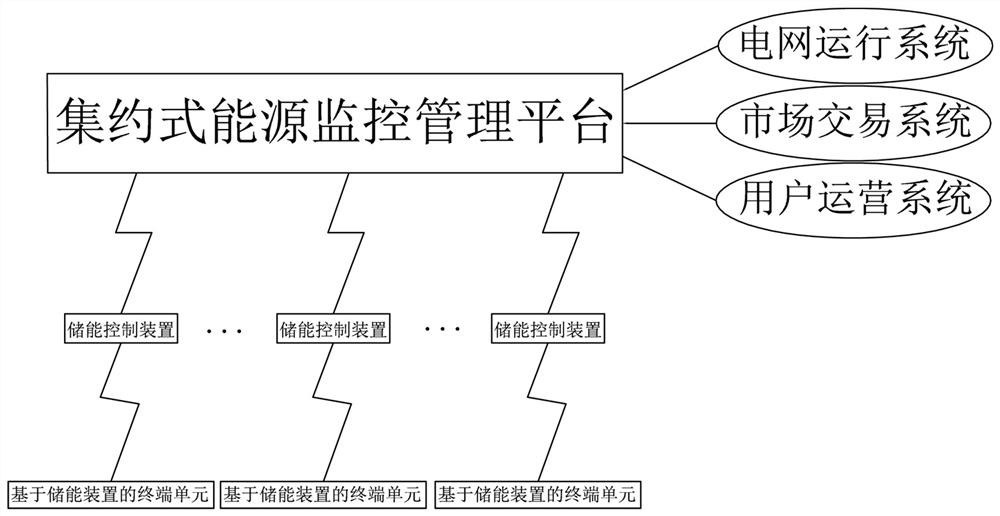
The invention discloses an energy monitoring and management system based on an energy storage device and a management method thereof, including a terminal unit based on an energy storage device, an energy control device, an intensive energy monitoring and management platform, a power grid operation system, a market transaction system and user operation system. The terminal unit based on the energy storage device is physically connected to the external power supply, and communicates with the energy control device in a wired or wireless manner; the energy control device communicates with the intensive energy monitoring and management platform in a wired or wireless manner; Wired or wireless communication connection; the intensive energy monitoring and management platform is connected to the grid operation system, the market transaction system and the user operation system respectively in a wired or wireless communication connection. The present invention can better improve the application efficiency of the energy storage device, better meet the electric energy demand on the user side, improve the level of energy utilization, and help improve social and economic benefits and environmental friendliness as a whole.

Description

Technical field [0001] The present invention relates to the field of energy Internet technologies, and more particularly to an energy monitoring management system based on an energy storage device and a management method thereof. Background technique [0002] The Energy Revolution promotes the establishment of energy Internet, and the energy storage is an important part of the energy Internet and key support technology, which is the hub of energy conversion and utilization. In October 2017, the National Development and Reform Commission and other five ministries issued a document "Guidance to promote the development of energy storage technology and industry", and deploy the energy storage industry at the national level. Among them, in order to further accelerate the development of the energy storage industry, it will promote the development of the energy storage industry in two stages in the next 10 years. The first stage (2017-2020) realizes that the energy storage is transition...

Claims


Application Information

Patent Timeline
Patent Type & Authority Patents(China)
IPC IPC(8): H02J3/32H02J13/00
CPCH02J13/0013H02J3/32Y04S20/12Y04S40/126Y02B90/20Y02E40/70Y04S10/50
Inventor 方日升余东旭方知进余勇铮谢涛彭翌春
Owner 方日升
Learn More