Power equipment transporting vehicle convenient to load and unload

A technology for power equipment and transport vehicles, which is applied in the direction of transportation and packaging, trolleys, motor vehicles, etc. It can solve the problems of power equipment falling to the ground, heavy weight of power equipment, and equipment falling to the ground, so as to achieve the effect of convenient handling and reduced height difference

Inactive Publication Date: 2018-09-18
STATE GRID CORP OF CHINA +1
View PDF5 Cites 15 Cited by
  • Summary
  • Abstract
  • Description
  • Claims
  • Application Information

AI Technical Summary

Problems solved by technology

Power equipment often needs to be assembled and installed on site. Since many power construction sites are in relatively remote places, large equipment cannot enter, and it is necessary to rely on manpower to transport the equipment to the construction site. The existing power equipment transport vehicles generally have relatively simple mechanisms , usually consists of handrails, bottom plates, and rollers. When transferring from a large transport vehicle to a power equipment transport vehicle, since the site of the large vehicle is relatively high, and the weight of the power equipment is generally heavy, it requires the cooperation of multiple people to move the power equipment. On the electric transport vehicle, once there is a coordination error, not only the equipment will fall from a high place, causing damage, but also the porter is likely to be injured, which is highly dangerous. Moreover, the locking device of the existing electric transport vehicle is relatively simple. When impacted, it is prone to slipping, causing the electrical equipment to fall to the ground

Method used


Image

  • Power equipment transporting vehicle convenient to load and unload
  • Power equipment transporting vehicle convenient to load and unload
  • Power equipment transporting vehicle convenient to load and unload

Examples


Embodiment

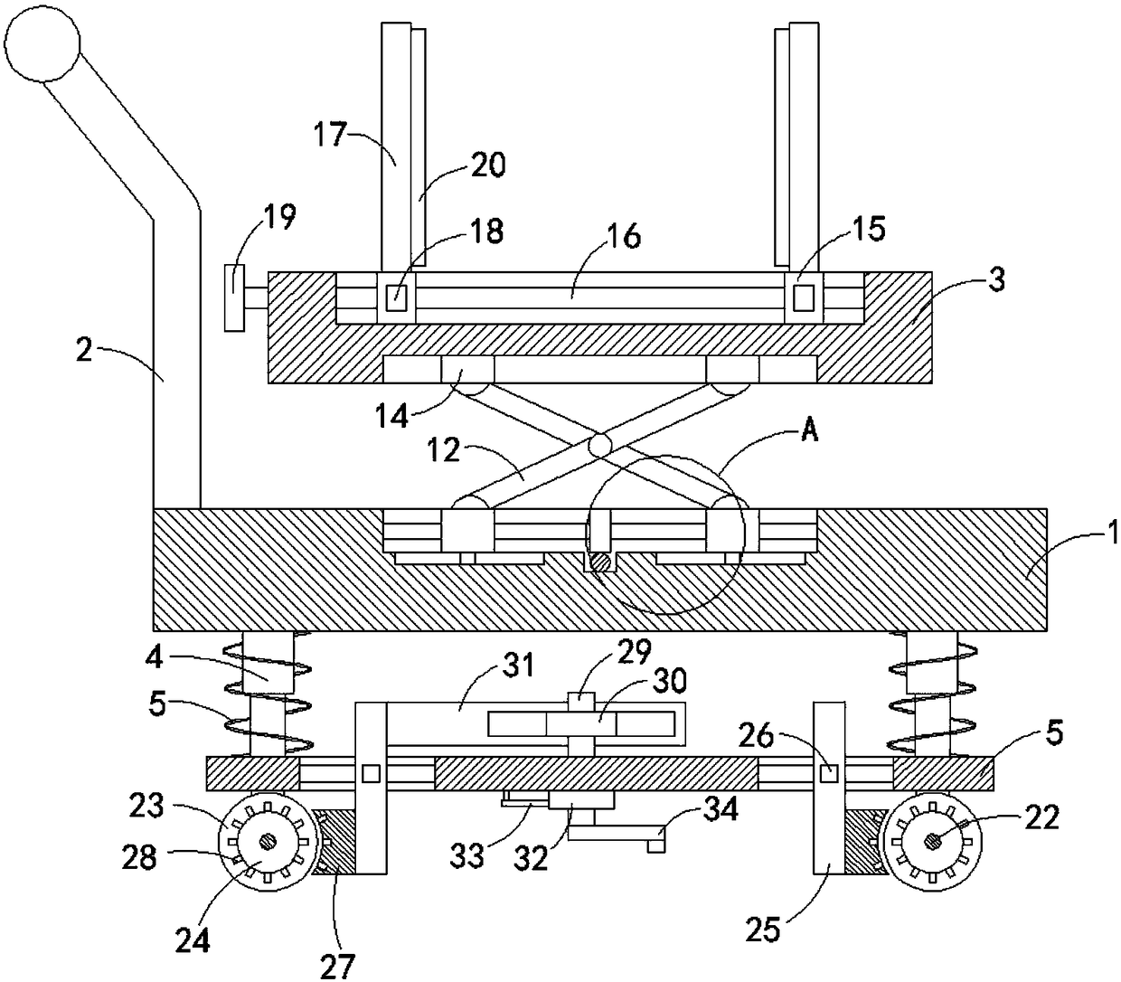
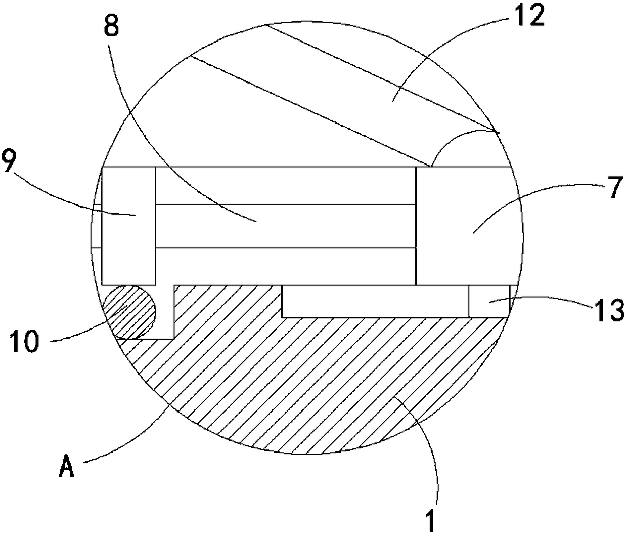
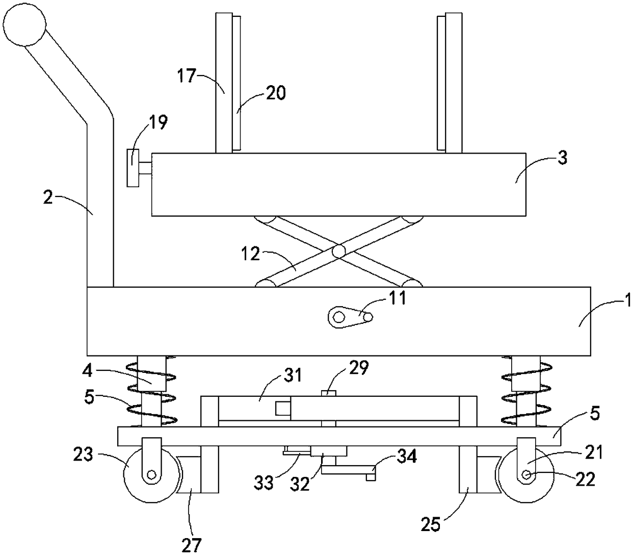
[0023] Such as Figure 1-3 As shown, a power equipment transport vehicle for easy loading and unloading includes a base 1, the upper end of the base 1 is fixedly connected with a handrail 2, the upper end of the base 1 is provided with a lifting plate 3, and a lifting mechanism is provided between the lifting plate 3 and the base 1, The upper end of the lifting plate 3 is provided with a clamping mechanism, the four corners of the lower end of the base 1 are fixedly connected with telescopic rods 4, the lower ends of multiple telescopic rods 4 are fixedly connected with the same mounting plate 5, and the outer casing of the telescopic rods 4 is connected with a spring 6, Both ends of the spring 6 are fixedly connected to the base 1 and the side walls of the mounting plate 5 respectively, and both sides of the lower end of the mounting plate 5 are provided with traveling mechanisms.

[0024] Wherein, the lifting mechanism includes a first groove arranged on the upper end of the...


PUM


Abstract

The invention belongs to the technical field of power equipment and in particular relates to a power equipment transporting vehicle convenient to load and unload. The power equipment transporting vehicle convenient to load and unload comprises a base; a handrail is fixedly connected to the upper end of the base; a lifting plate is arranged at the upper end of the base; a lifting mechanism is arranged between the lifting plate and the base; a clamping mechanism is arranged at the upper end of the lifting plate; telescopic rods are fixedly connected to the four corners of the lower end of the base; a same mounting plate is fixedly connected to the lower ends of the multiple telescopic rods; springs sleeving the telescopic rods; the two ends of the spring are fixedly connected with the base and the mounting plate; and running mechanisms are arranged on the two sides of the lower end of the mounting plate. The power equipment transporting vehicle convenient to load and unload has the advantages that the height difference between the power equipment transporting vehicle and a large-sized transporting vehicle is reduced by using the lifting plate to be convenient for conveying and transferring power equipment; as the clamping plate is arranged, the power equipment is convenient to clamp and fix so that additional fixing tools such as ropes do not need to use; and the vehicle is simple and convenient.

Description

technical field [0001] The invention belongs to the technical field of electric equipment, and in particular relates to an electric equipment transport vehicle which is convenient for loading and unloading. Background technique [0002] Power equipment mainly includes power generation equipment and power supply equipment. Power generation equipment is mainly power plant boilers, steam turbines, gas turbines, water turbines, generators, transformers, etc. Power supply equipment is mainly transmission lines of various voltage levels, transformers, contactors, etc. device and so on. Power equipment often needs to be assembled and installed on site. Since many power construction sites are in relatively remote places, large equipment cannot enter, and it is necessary to rely on manpower to transport the equipment to the construction site. The existing power equipment transport vehicles generally have relatively simple mechanisms , usually consists of handrails, bottom plates, an...

Claims


Application Information

Patent Timeline
Patent Type & Authority Applications(China)
IPC IPC(8): B62B3/02B62B3/04B62B5/04
CPCB62B3/02B62B3/04B62B5/0442B62B2203/10B62B2203/70
Inventor 丁路勇
Owner STATE GRID CORP OF CHINA
Why Eureka
Try Eureka