Bicycle with easy adjustment of riding posture and driving direction
A technology of driving direction and bicycle, which is applied in the directions of bicycle accessories, steering mechanism, transportation and packaging, etc. It can solve the problems that affect the user's riding comfort, do not involve handlebar adjustment, adjust the riding posture, etc., to improve the riding experience , avoid back pain and discomfort, and can be adjusted in a large range
- Summary
- Abstract
- Description
- Claims
- Application Information
AI Technical Summary
Problems solved by technology
Method used
Image
Examples
Embodiment 1
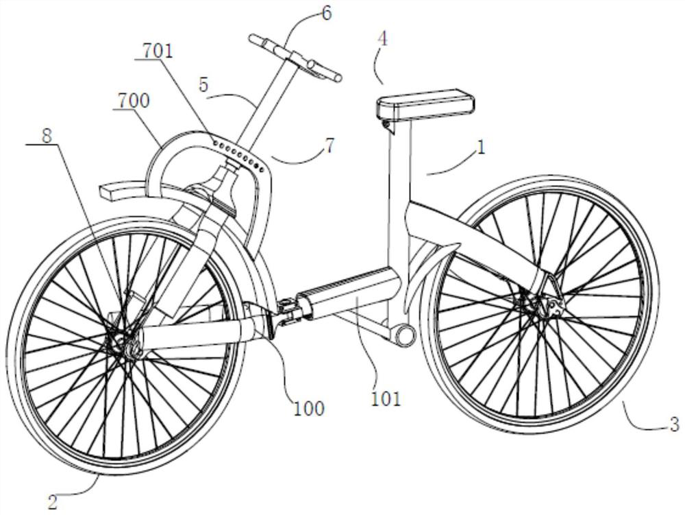
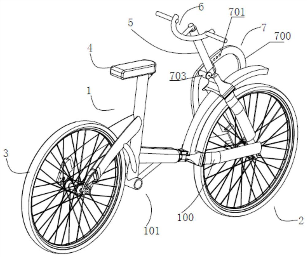
[0039] see Figure 1 ~ Figure 3 as well as Figure 6 As shown, the present invention provides a bicycle with easy adjustment of riding posture and driving direction, comprising a frame unit 1 and a seat 4 arranged on the frame unit 1, a drive unit, a front wheel unit 2 and a rear wheel unit 3; a front fork 5, one end of the front fork 5 is connected on the central axis of the front wheel unit 2, and also includes a handlebar assembly 6 which can be turned over at a certain angle in the direction of travel of the front wheel unit 2 linked with the front fork 5, and used The locking mechanism 7 is in the overturned state of locking the handlebar assembly 6 .
[0040] After adopting the above structure, compared with the handlebar assembly of a traditional bicycle, which can only drive the front fork to deflect left and right to control the direction of travel, the handlebar assembly 6 of the bicycle disclosed in the present invention can be turned forward or backward to a certa...
Embodiment 2
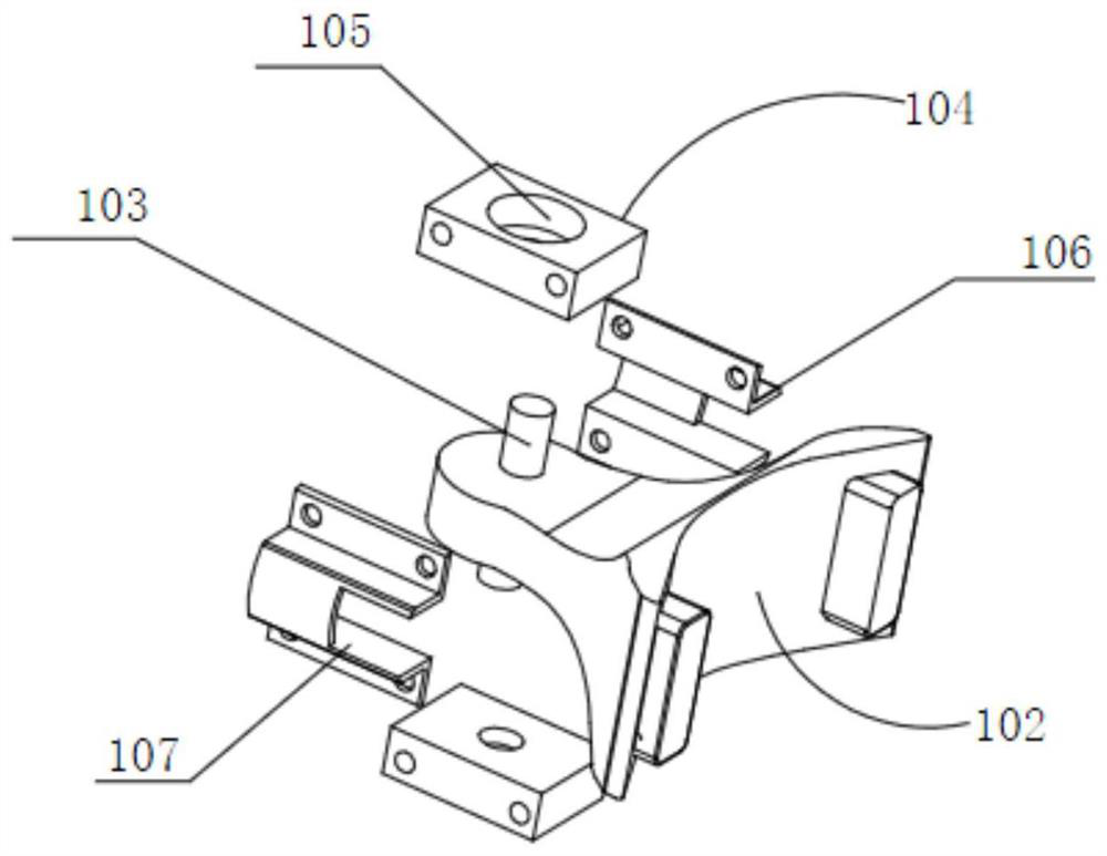
[0048] see Figure 3 ~ Figure 5 as well as Figure 6 Shown, the present invention provides another kind of bicycle that riding posture and driving direction are easy to adjust, and it comprises a vehicle frame unit 1 and the seat 4 that is arranged on the vehicle frame unit 1, drive unit, front wheel unit 2 and rear Wheel unit 3; a front fork 5 and the handlebar assembly 6 that is connected to the front fork 5 upper ends; Its vehicle frame unit 1 is to comprise front vehicle frame 100 and rear vehicle frame 101 equally, and front vehicle frame 100 and rear vehicle frame 101 can be Rotation connection; front wheel unit 2 is rotatably connected to the front vehicle frame 100, and the lower end of the front fork 5 is rotatably connected to the central shaft 8 of the front wheel unit 2; the front vehicle frame 100 is provided with a locking mechanism 7, locked The mechanism 7 is used to lock the front fork 5 on the front frame 100 after the front fork 5 rotates a certain angle ar...
Embodiment 3
[0050] Such as Figure 7 as shown,
[0051] The front frame 100 and the rear frame 101 are rotatably connected, and the front fork 5 is fixedly connected to the front frame 100; the lower end of the handle device 6 is rotatably connected to the upper end of the front fork 5 through a rotating shaft 600, so The above-mentioned locking mechanism 7 is used to lock the handle device 6 on the front frame 100 after the handle device 6 rotates a certain angle around its rotating shaft 600 . The handle device 6 can rotate around the rotating shaft 600 at the lower end of the handle device 6. When turning to a suitable angle, the locking mechanism 7 locks the handle device 6 on the front frame 100. Since the front frame 100 and the rear frame 101 can Rotation connection, so when the handle device 6 drives the front fork 5 to rotate, the front frame 100 together with the front wheel unit 2 can rotate an angle relative to the rear frame 101, thereby facilitating the direction of rotatio...
PUM
 Abstract
Description
Claims
Application Information
 - R&D
- Intellectual Property
- Life Sciences
- Materials
- Tech Scout
- Unparalleled Data Quality
- Higher Quality Content
- 60% Fewer Hallucinations
Browse by: Latest US Patents, China's latest patents, Technical Efficacy Thesaurus, Application Domain, Technology Topic, Popular Technical Reports.
© 2025 PatSnap. All rights reserved.Legal|Privacy policy|Modern Slavery Act Transparency Statement|Sitemap|About US| Contact US: help@patsnap.com


