
Waste steel heating furnace

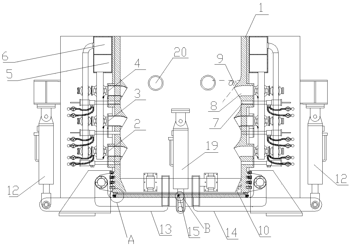
A heating furnace and scrap steel technology, which is applied in the field of scrap steel heating furnaces, can solve the problems of uneven heating, low safety and small bearing capacity, and achieve the effects of prolonging service life, improving heating efficiency and reducing wear rate.

Pending Publication Date: 2018-09-18
张会强
View PDF0 Cites 3 Cited by
  • Summary
  • Abstract
  • Description
  • Claims
  • Application Information

AI Technical Summary

Problems solved by technology

[0003] The existing steel scrap heating furnace has small loading capacity, uneven heating, low gas utilization rate, serious material leakage, and severe impact from falling scrap steel, high burner nozzle wear rate, and easy deformation of the furnace body. The feeding and discharging of the heating furnace share a material opening
When unloading, the crane needs to be hoisted for inclined unloading. The operation is cumbersome, time-consuming and labor-intensive, and the pollution is large, the material leakage is serious, and the safety is not high.

Method used


Image

  • Waste steel heating furnace
  • Waste steel heating furnace
  • Waste steel heating furnace

Examples


Embodiment Construction

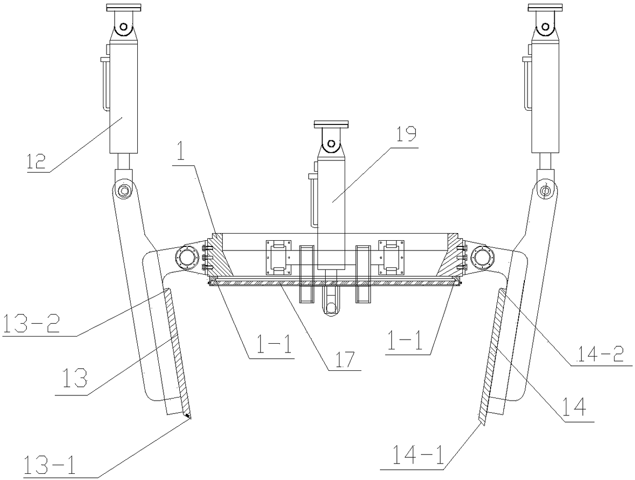
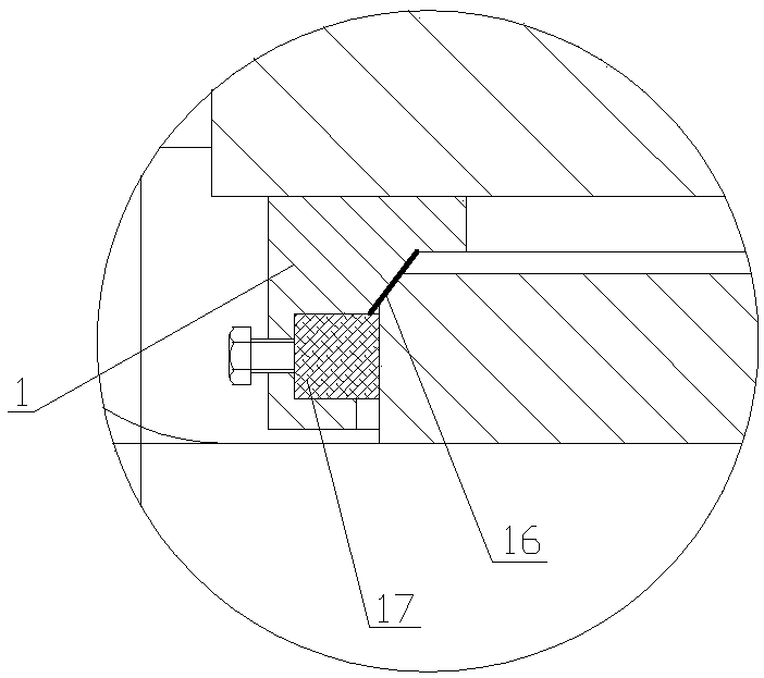
[0043] In order to further explain the technical means and effects of the present invention to achieve the intended purpose of the invention, the specific implementation, structure, characteristics and details of a scrap steel heating furnace proposed according to the present invention will be described below in conjunction with the accompanying drawings and preferred embodiments. Its effect is described in detail below.

[0044] In the description of the present invention, it should be noted that the terms indicating the orientation, such as: up, down, left, right, etc., are all based on the orientation or positional relationship shown in the drawings, and are only for the convenience of describing the present invention. and simplified descriptions, rather than indicating or implying that the device or element referred to must be constructed and operated in a specific orientation, in a specific orientation, and thus should not be construed as limiting the invention.

[0045] ...


PUM


Abstract

The invention relates to a waste steel heating furnace. The waste steel heating furnace comprises a furnace body and a split type flap valve arranged at the bottom of the furnace body, the upper partof the furnace body communicates with the lower part of the furnace body, a plurality of layers of combustors are arranged on the two side surfaces of the furnace body, and each combustor communicateswith an air annular pipeline and a coal gas annular pipeline; an automatic ignition hole is formed in the lower portion of each combustor, the combustors are provided with protective caps, and the protective caps are located above the automatic ignition holes; the automatic ignition holes are flush with the inner wall of the furnace body, protective cap shells extend into the furnace body, and the tops of the protective caps are bent downwards and are in an arc transition; the included angle alpha between the inclined furnace wall at the upper end of each protective cap and the horizontal direction is 30-60 degrees, the inner wall of the bottom of the furnace body is parallel to the vertical direction or is inclined to a certain angle towards the inside of the furnace body, and the inclination angle beta is 0-45 degrees; and the two side surfaces of the furnace body are provided with reinforcing ribs which are distributed in a cross-shaped manner, and the combustors are located at thecross-shaped intersection points of the reinforcing ribs. The waste steel heating furnace is uniform in heating, high in efficiency, small in pollution and high in safety, so that the wear rate of the combustors is reduced, and the service life of the combustors is prolonged.

Description

technical field [0001] The invention belongs to the technical field of scrap steel baking, in particular to a scrap steel heating furnace. Background technique [0002] In iron and steel production, in order to save energy and reduce consumption, it is usually necessary to preheat scrap steel. In terms of economic benefits, on the one hand, heating scrap steel can greatly reduce the energy consumption of the converter. The reduction of production and maintenance costs, the increase of output, and the improvement of steel quality all contribute to different degrees, and the comprehensive economic benefits are huge. [0003] The existing steel scrap heating furnace has small loading capacity, uneven heating, low gas utilization rate, serious material leakage, and severe impact from falling scrap steel, high burner nozzle wear rate, and easy deformation of the furnace body. The feeding and discharging of the heating furnace share a material opening. When unloading, the crane ...

Claims


Application Information

Patent Timeline
IPC IPC(8): F27D13/00F27D99/00C21C5/46
CPCF27D13/002F27D99/0033C21C5/46Y02P10/20
Inventor 张会强
Owner 张会强
Learn More