Supercharge Your Innovation With Domain-Expert AI Agents!

Machine vision based camera defect detection method

A defect detection and machine vision technology, applied in the testing of machines/structural components, optical instrument testing, instruments, etc., can solve problems such as low work efficiency, mirror surface glue overflow, scratches, etc., to improve efficiency and preparation rate, save The effect of human cost

Inactive Publication Date: 2018-09-18
深圳市锐光科技有限公司
View PDF6 Cites 5 Cited by
  • Summary
  • Abstract
  • Description
  • Claims
  • Application Information

AI Technical Summary

Problems solved by technology

Then in the production process, some cameras will have defects such as edge overflow, mirror overflow, scratches, wear and other defects. Since the previous defect detection work was done manually, the work efficiency is extremely low.

Method used


Image

  • Machine vision based camera defect detection method
  • Machine vision based camera defect detection method
  • Machine vision based camera defect detection method

Examples


Embodiment Construction

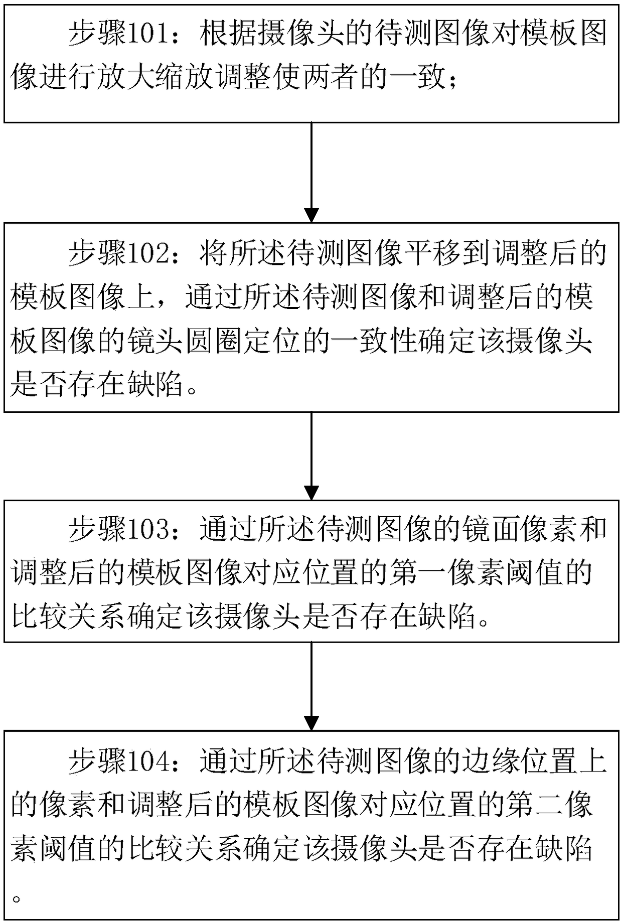
[0025] In order to make the object, technical solution and advantages of the present invention clearer, the present invention will be further described in detail below in conjunction with the accompanying drawings and embodiments. It should be understood that the specific embodiments described here are only used to explain the present invention, not to limit the present invention.

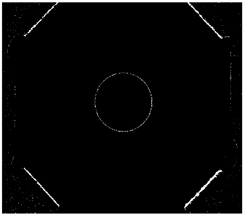
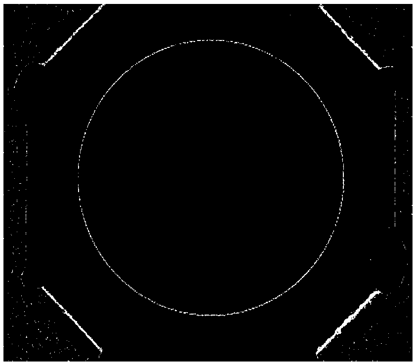
[0026] The camera defect detection technology based on machine vision of the present invention uses template matching and positioning based on gray value sub-pixels. In order not to be affected by factors such as illumination, the gray value of the template must be normalized first, and the image to be tested must be translated to In the template ROI image, calculate the sum of the absolute values ​​of the differences between them. When the sum exceeds a certain range, it is regarded as a defective product, and then these feature points with obvious differences are calculated into a connected domain...


PUM


Abstract

The invention discloses a machine vision based camera defect detection method. According to a to-be-detected image of a camera, a template image is zoomed to be consistent with the to-be-detected image; and the to-be-detected image is translated to the adjusted template image, and whether the camera is defective is determined through the consistency of lens circle positioning of the to-be-detectedimage and the adjusted template image. The detection method can highly effectively improve the efficiency and preparation rate of camera defect detection, thereby greatly saving the labor cost.

Description

technical field [0001] The invention belongs to the technical field of intelligent detection, and in particular relates to a camera defect detection method based on machine vision. Background technique [0002] At present, we have entered the era of Industry 4.0. In this era, only the development of intelligent manufacturing can meet the needs of modern industry. The core technology of the Industry 4.0 era is machine vision. Machine vision technology is one of the greatest technologies of human beings in the 20th century. In front of us, the amount of information contained in images is very rich. We need to use modern technology to mine, so that machines can also perceive external information, so as to help humans accomplish more things, and even accomplish some things that humans cannot accomplish. [0003] At present, the application fields of cameras are more and more extensive, and the demand is also increasing. Then, in the production process, some cameras will have d...

Claims


Application Information

Patent Timeline
Patent Type & Authority Applications(China)
IPC IPC(8): G01M11/00
Inventor 林澎聪
Owner 深圳市锐光科技有限公司
Features
  • R&D
  • Intellectual Property
  • Life Sciences
  • Materials
  • Tech Scout
  • Unparalleled Data Quality
  • Higher Quality Content
  • 60% Fewer Hallucinations
Learn More