Electric power cabinet having dedusting and heat radiation functions

A power cabinet and functional technology, applied in the direction of electrical components, substation/power distribution device casing, substation/switch layout details, etc., can solve the problems of damage to electrical equipment, dust floating in, limited heat dissipation efficiency, etc., to ensure the working state , prolong service life, high heat dissipation effect

Pending Publication Date: 2018-09-18
KUNMING UNIV OF SCI & TECH
View PDF0 Cites 21 Cited by
  • Summary
  • Abstract
  • Description
  • Claims
  • Application Information

AI Technical Summary

Problems solved by technology

[0002] The power cabinet is the cabinet where the power equipment is installed. When the power equipment is running, it will generate a lot of heat. The heat needs to be discharged from the cabinet in time. Otherwise, the heat will accumulate, which will easily cause the aging of the power equipment, and even high temperature will damage the power equipment, and may cause an explosion. Dangerous; the traditional power cabinet simply has cooling holes around the cabinet for heat dissipation. The opening of these cooling holes not only has a very limited heat dissipation efficiency, but also cannot discharge the heat from the cabinet in time, and it is easy for dust to float into the power supply. Cabinets, dust accumulation on the surface of power equipment not only accelerates the aging of equipment, but also easily causes equipment damage and increases maintenance costs

Method used


Image

  • Electric power cabinet having dedusting and heat radiation functions
  • Electric power cabinet having dedusting and heat radiation functions
  • Electric power cabinet having dedusting and heat radiation functions

Examples


Embodiment 1

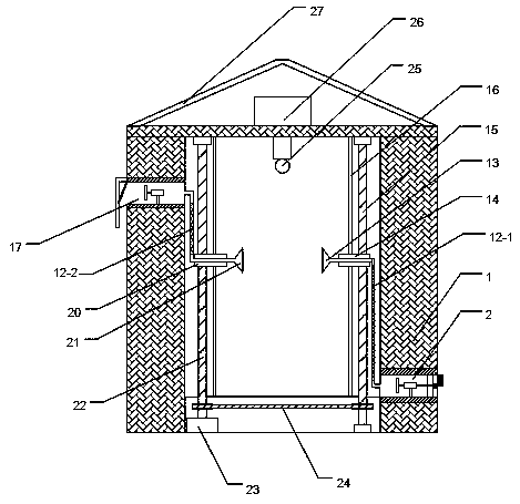
[0024] Embodiment 1: as Figure 1-Figure 3 As shown, a power cabinet with dust removal and heat dissipation functions includes a cabinet body 1, and also includes an air intake device 2, an exhaust device 17 and a battery 26;

[0025] The storage battery 26 is used to supply power to the air intake device 2 and the exhaust device 17, the air intake device 2 is installed under one side of the cabinet body 1 for drawing external air into the cabinet body 1, and the exhaust device 17 is installed in the cabinet body 1 The upper side of the other side is used to suck the gas in the cabinet 1 to achieve dust removal and heat dissipation.

[0026] Further, a dust-proof device may be provided, and the dust-proof device is installed at the air intake pipe 3 of the air intake device 2 to remove dust from the gas entering from the outside.

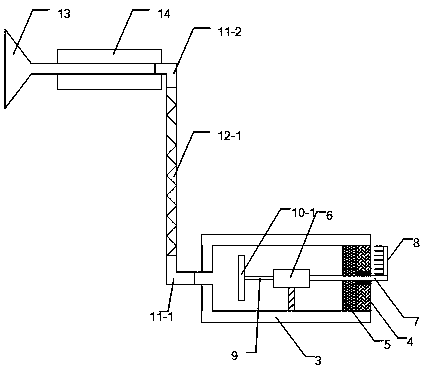
[0027] Further, the air intake device can be set to include air intake pipe 3, biaxial motor 6, right shaft 7, left shaft 9, fan blade I10-1, righ...


PUM


Abstract

The invention discloses an electric power cabinet having dedusting and heat radiation functions. The electric power cabinet comprises a cabinet body and further comprises an air inlet device, an exhaust device and a storage battery, wherein the storage battery is used for supplying power for the air inlet device and the exhaust device, the air inlet device is arranged at a lower portion of one side of the cabinet body and is used for pumping the external air into the cabinet body, and the exhaust device is mounted at the other side of the cabinet body and is used for pumping the air in the cabinet body to realize dedusting and heat radiation. The electric power cabinet is advantaged in that through arranging an air blowing bucket and an air collection bucket which are opposite to each other, the air is quickly convected in the cabinet, heat is efficiently taken away from the inside of the cabinet, heat radiation efficiency is high, the service life of the equipment is prolonged, moreover, dusts in the cabinet are efficiently sucked, the equipment is kept to be clean, the working state of the equipment is guaranteed, the incoming air is filtered through a dust net and sponge blockswhich are arranged, the convective gas is guaranteed to be dry and dust free, and the dust and the moisture are prevented from entering into electrical equipment.

Description

technical field [0001] The invention relates to a power cabinet with dust removal and heat dissipation functions, belonging to the field of power equipment. Background technique [0002] The power cabinet is the cabinet where the power equipment is installed. When the power equipment is running, it will generate a lot of heat. The heat needs to be discharged from the cabinet in time. Otherwise, the heat will accumulate, which will easily cause the aging of the power equipment, and even high temperature will damage the power equipment, and may cause an explosion. Dangerous; the traditional power cabinet simply has cooling holes around the cabinet for heat dissipation. The opening of these cooling holes not only has a very limited heat dissipation efficiency, but also cannot discharge the heat from the cabinet in time, and it is easy for dust to float into the power supply. Cabinets, dust accumulation on the surface of power equipment not only accelerates the aging of equipmen...

Claims


Application Information

Patent Timeline
Patent Type & Authority Applications(China)
IPC IPC(8): H02B1/56H02B1/28
CPCH02B1/28H02B1/565
Inventor 李士伟
Owner KUNMING UNIV OF SCI & TECH
Why Eureka
Try Eureka