Garbage separating device and garbage moistening and separating device
A separation device and technology for garbage, applied in solid separation, separation of solids from solids by air flow, chemical instruments and methods, etc., can solve the problems of difficult plastic sorting, environmental pollution, waste of resources, etc.
- Summary
- Abstract
- Description
- Claims
- Application Information
AI Technical Summary
Problems solved by technology
Method used
Image
Examples
Embodiment 1
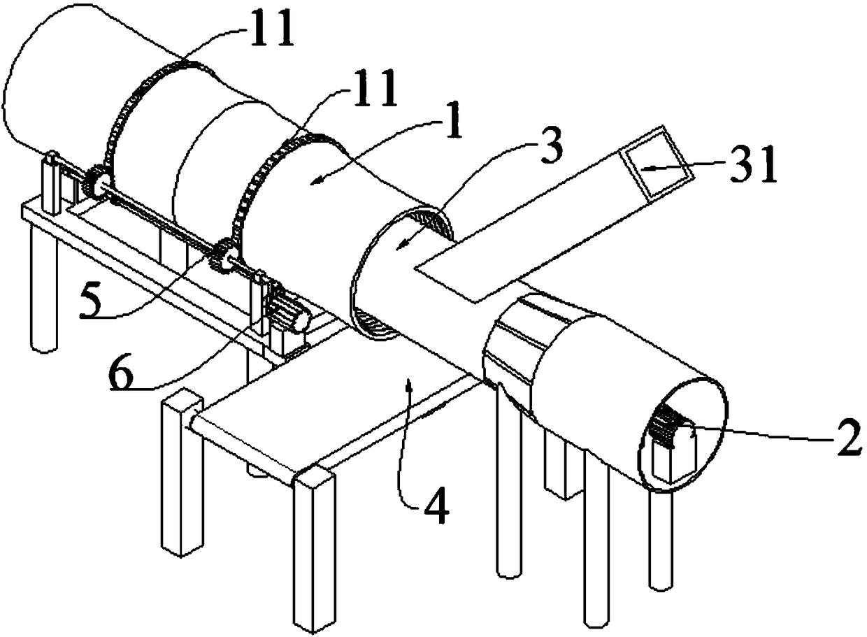
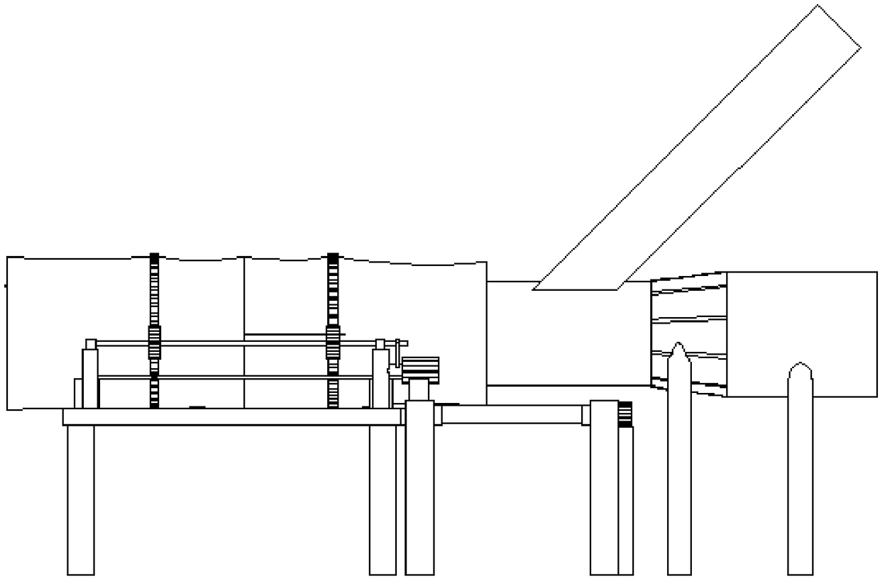
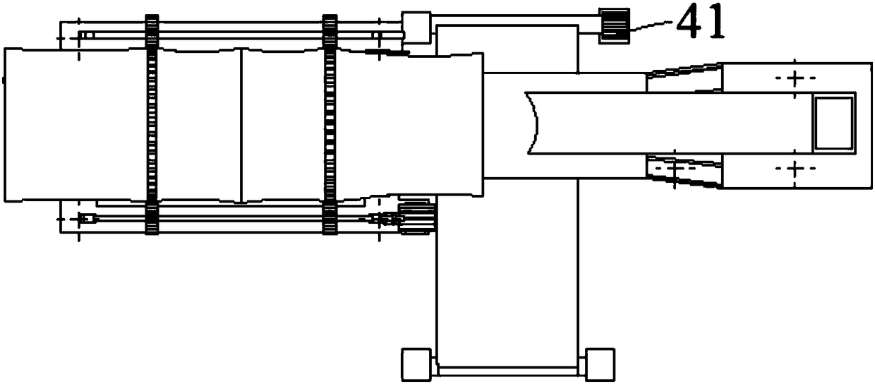
[0032] A garbage separation device, such as Figure 1-3 As shown, it includes a garbage conveying mechanism 1 and a fan 2; the transportation direction of the garbage conveying mechanism 1 is opposite to the blowing direction of the fan 2; the garbage conveying mechanism 1 is located within the wind range of the fan 2.
[0033] In the optional technical solution of this embodiment, a garbage transfer cylinder 3 is also included, the outlet of the garbage transfer cylinder 3 extends into the garbage conveying mechanism 1 , and the fan 2 is directly opposite to the garbage transfer cylinder 3 .
[0034] In an optional technical solution of this embodiment, the outlet of the garbage transfer cylinder 3 extends into the middle of the garbage conveying mechanism 1 .
[0035] In an optional technical solution of this embodiment, the garbage transfer cylinder 3 is connected to an obliquely arranged garbage transportation pipe 31 .
[0036] In an optional technical solution of this e...
Embodiment 2
[0042] On the basis of Example 1, such as Figure 4 As shown, along the transporting direction of the refuse conveying mechanism 1, a heavy object conveying mechanism 4 is provided at the rear end of the refuse conveying mechanism 1 .
[0043] In an optional technical solution of this embodiment, a heavy object collection box may be provided at the delivery outlet of the heavy object transmission mechanism 4 . Preferably, the weight conveying mechanism 4 is a conveyor belt, and the conveyor belt is driven by a second driving mechanism 41, and the second driving mechanism 41 is preferably a motor.
[0044] In an optional technical solution of this embodiment, a plastic collection net 8 is provided at the front end of the garbage conveying mechanism 1 along the transport direction of the garbage conveying mechanism 1 .
Embodiment 3
[0046] A garbage wetting and separating device, comprising a garbage wetting device and the garbage separating device of Embodiment 1 or Embodiment 2 above; the garbage outlet of the garbage wetting device is connected to a garbage conveying mechanism 1 . The rubbish wetting device can be an existing device, such as a sprinkler head, a pool, etc. that can wet the rubbish; if the rubbish wetting device is a pool, the step of filtering water can be added before the rubbish is soaked and transported to the rubbish conveying mechanism 1. Therefore, this garbage wet separation device includes the benefits of the above garbage separation device, which will not be repeated here; in addition, this garbage wet separation device can also soak the paper, fabric, etc. in the garbage to prevent the fan from blowing the paper. Parts are blown out, thereby achieving better sorting of plastics.
[0047]As a further technical solution, the garbage wetting device may also be a garbage bag crush...
PUM
 Abstract
Description
Claims
Application Information
 - R&D
- Intellectual Property
- Life Sciences
- Materials
- Tech Scout
- Unparalleled Data Quality
- Higher Quality Content
- 60% Fewer Hallucinations
Browse by: Latest US Patents, China's latest patents, Technical Efficacy Thesaurus, Application Domain, Technology Topic, Popular Technical Reports.
© 2025 PatSnap. All rights reserved.Legal|Privacy policy|Modern Slavery Act Transparency Statement|Sitemap|About US| Contact US: help@patsnap.com


