Blade tip clamping device

A technology of clamping device and blade tip, applied in the field of blade tip clamping device, can solve the problems of welding stress, welding deformation, poor welding strength, etc., and achieve the effect of reducing welding stress and high welding precision

Inactive Publication Date: 2018-09-21
余燕
View PDF0 Cites 2 Cited by
  • Summary
  • Abstract
  • Description
  • Claims
  • Application Information

AI Technical Summary

Problems solved by technology

[0003] Aiming at the deficiencies in the prior art, the purpose of the present invention is to provide a blade tip clamping device to solve the problem that the common clamping device in the current technology only clamps the blade tip without damaging the blade. With a simple clamping, it is impossible to weld and repair the blades by yourself. It is necessary to use an external handheld welding device, which has a single performance, and the welding accuracy of the handheld device is low, and the welding strength is poor. During welding, the blades will be heated unevenly, resulting in welding stress , leading to the problem of welding deformation

Method used


Image

  • Blade tip clamping device
  • Blade tip clamping device
  • Blade tip clamping device

Examples


Embodiment Construction

[0022] In order to make the technical means, creative features, goals and effects achieved by the present invention easy to understand, the present invention will be further described below in conjunction with specific embodiments.

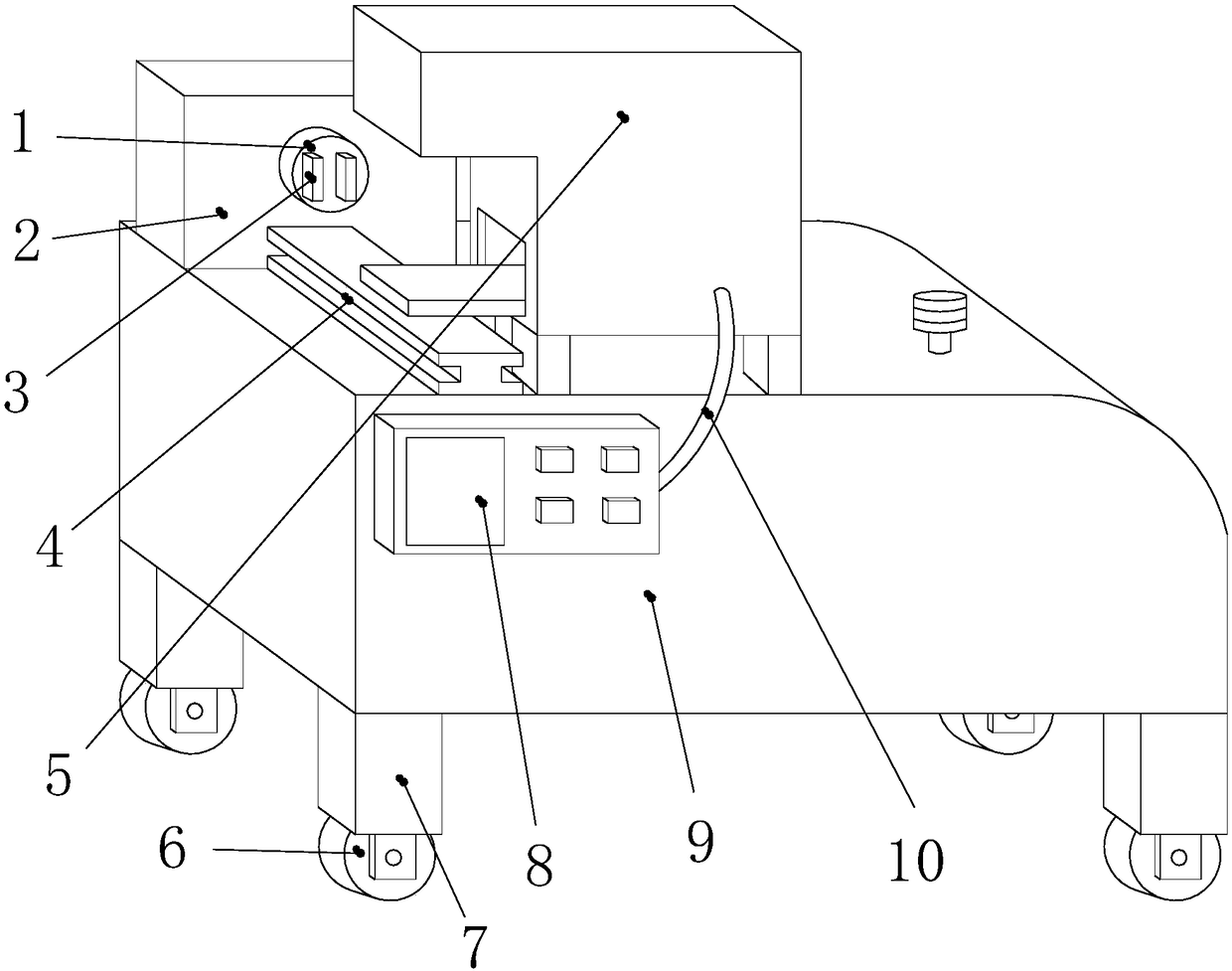
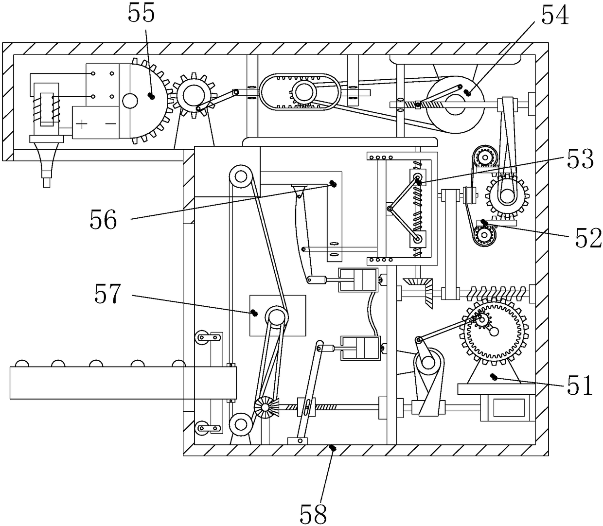
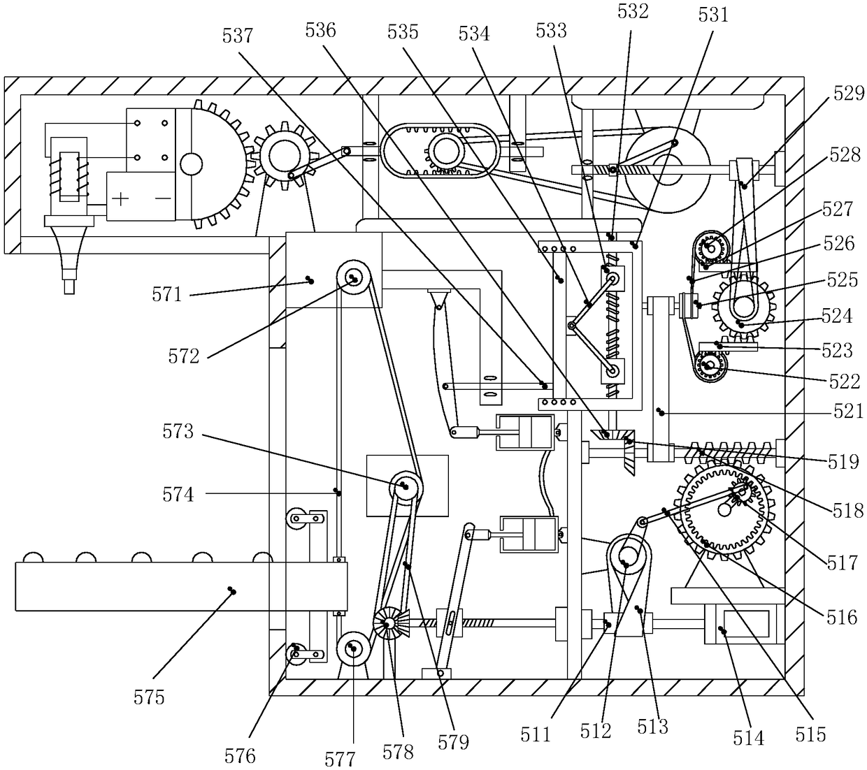
[0023] see Figure 1-Figure 4 , the present invention provides a blade tip clamping device: its structure includes a rotating clamping seat 1, a sliding seat 2, a blade clamping plate 3, a slide rail 4, an ultrasonic welding protection device 5, casters 6, pads 7, and a control panel 8. The main body of the device 9 and the transmission wire 10. There are more than two pads 7 with the same shape and size. The pads 7 are welded to the four corners of the lower surface of the main body 9 of the device. The casters 6 are movably connected to the The lower end of the pad 7, the control panel 8 is fixed on the upper end of the front of the device main body 9 by screws, the left end of the transmission wire 10 is glued to the right end of the control pa...


PUM


Abstract

The invention discloses a blade tip clamping device. The blade tip clamping device structurally comprises a rotating clamping seat, a sliding seat, a blade clamping plate, an ultrasonic wave welding protecting device, castors, at least two cushion blocks, a control panel, a device main body and a transmission lead, wherein the cushion blocks are in same shape and size and are welded to four corners of the lower surface of the device main body, and the castors are movably connected to the lower ends of the cushion blocks. By arranging the ultrasonic wave welding protecting device, the lower endof a blade is supported through the cooperation with a lifting support plate during the welding, so that the situation that the tip of the blade is damaged due to an overhigh clamping stress when theblade is overweight is prevented; and the welded part of the blade is supported, so that the welding stress borne by the blade is reduced, the deformation of the formation of the blade is controlledwithin a tolerance range, the welding strength of the welded blade can approximate to the strength of a raw material, the welding precision is high, and the subsequent use of the blade is not influenced.

Description

technical field [0001] The invention relates to a blade tip clamping device, which belongs to the field of blades and clamping devices. Background technique [0002] When maintaining and processing the blades, in order to facilitate the work, the blades need to be fixed, which requires a clamping device. The clamping device used in the current technology is only used when clamping the tip of the blade. Carry out a simple clamping of the blade without damaging the blade, and the blade cannot be welded and repaired by itself. It is necessary to use an external handheld welding device, which has a single performance, and the welding accuracy of the handheld device is low, and the welding strength is poor. The blades are heated unevenly, resulting in welding stress and welding deformation. Contents of the invention [0003] Aiming at the deficiencies in the prior art, the purpose of the present invention is to provide a blade tip clamping device to solve the problem that the ...

Claims


Application Information

Patent Timeline
Patent Type & Authority Applications(China)
IPC IPC(8): B23K20/10
CPCB23K20/10
Inventor 余燕李彷徨
Owner 余燕
Why Eureka
Try Eureka