Welding positioning tool clamp

A tooling, welding positioning technology, applied in manufacturing tools, welding equipment, auxiliary welding equipment, etc., can solve the problems of eccentricity, offset between the steel plate and the screw, the two steel plates are not parallel, the operator is dangerous, etc., to achieve stable clamping , to ensure the welding quality, convenient and precise welding effect

Inactive Publication Date: 2018-09-21
SUZHOU ZHONGSHUNRUITAI AUTOMOBILE INSPECTION TOOLS CO LTD
View PDF0 Cites 6 Cited by
  • Summary
  • Abstract
  • Description
  • Claims
  • Application Information

AI Technical Summary

Problems solved by technology

[0002] Auto parts processing is the various units that constitute the overall processing of auto parts and the products that serve the processing of auto parts. In the process of processing, welding is a very important part. Welding is also called welding and welding. Or the manufacturing process and technology of joining metal or other thermoplastic materials such as plastics in a high-pressure way. There are many energy sources for modern welding, including gas flames, electric arcs, lasers, electron beams, friction and ultrasonic waves. In addition to being used in factories, Welding can also be carried out in a variety of environments. No matter where, welding may bring danger to the operator, so appropriate protective measures must be taken when welding. In the automobile production industry, there is a support that is composed of two pieces The steel plate and the screw are welded together. The screw is welded between two parallel steel plates. Since the screw is round, during the welding process, the steel plate and the screw will be eccentric or offset, or two steel plates will be found after welding. If they are not parallel, the workpiece will be scrapped. For this reason, we propose a welding positioning fixture to solve the above problems

Method used


Image

  • Welding positioning tool clamp
  • Welding positioning tool clamp
  • Welding positioning tool clamp

Examples


Embodiment Construction

[0016] The following will clearly and completely describe the technical solutions in the embodiments of the present invention with reference to the accompanying drawings in the embodiments of the present invention. Obviously, the described embodiments are only some, not all, embodiments of the present invention.

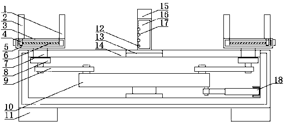
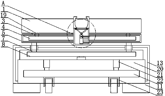
[0017] refer to Figure 1-3 , a fixture for welding and positioning, including a mounting block 13, grooves 20 are provided on both sides of the lower end of the mounting block 13, which is convenient for installation, a moving device is provided in the groove 20, and it is convenient to move. cavity, the bottom of the installation cavity is rotatably connected with a turntable 10, and one end side wall of the installation cavity is rotatably connected with a first oil cylinder 18, the end of the piston rod of the first oil cylinder 18 is rotatably connected to the lower end side of the turntable 10, the first oil cylinder 10 Push the turntable 10 to rotate, so that ...


PUM


Abstract

The invention discloses a welding positioning tool clamp which comprises an installing block. Grooves are formed in the two sides of the lower end of the installing block, movement devices are arranged in the grooves, an installing cavity is arranged in the installing block, a rotary disc is rotationally connected to the bottom of the interior of the installing cavity, a first oil cylinder is rotationally connected to the side wall of one end of the interior of the installing cavity, the tail end of a piston rod of the first oil cylinder is rotationally connected with one side of the lower endof the rotary disc, first pull rods are rotationally connected to the two sides of the upper end of the rotary disc, and a second connecting plate is rotationally connected to one side of the upper end of each first pull rod. By means of the welding positioning tool clamp, a steel plate can be stably clamped, the accurate welding function is facilitated, the steel plate can be fixed, the positionrelationship between a screw and the steel plate is conveniently adjusted, fixation can be carried out, eccentricity and offset can be avoided when a worker conducts welding, the welding quality is guaranteed, operation is facilitated, and the welding positioning tool clamp is suitable for popularization.

Description

technical field [0001] The invention relates to the technical field of welding positioning fixtures, in particular to a welding positioning fixture. Background technique [0002] Auto parts processing is the various units that constitute the overall processing of auto parts and the products that serve the processing of auto parts. In the process of processing, welding is a very important part. Welding is also called welding and welding. Or the manufacturing process and technology of joining metal or other thermoplastic materials such as plastics in a high-pressure way. There are many energy sources for modern welding, including gas flames, electric arcs, lasers, electron beams, friction and ultrasonic waves. In addition to being used in factories, Welding can also be carried out in a variety of environments. No matter where, welding may bring danger to the operator, so appropriate protective measures must be taken when welding. In the automobile production industry, there is...

Claims


Application Information

Patent Timeline
Patent Type & Authority Applications(China)
IPC IPC(8): B23K37/04
CPCB23K37/0443
Inventor 蔡永忠
Owner SUZHOU ZHONGSHUNRUITAI AUTOMOBILE INSPECTION TOOLS CO LTD
Why Eureka
Try Eureka