Large-power turning and milling composite machine tool

A compound machine tool and high-power technology, applied in the field of machine tools, can solve the problems of inability to realize high-power machining, inability to install large tools, and many times of workpiece clamping, so as to reduce the workshop area and equipment maintenance costs, and improve machining Accuracy, the effect of reducing the number of clamping times

Pending Publication Date: 2018-09-21
津上精密机床(浙江)有限公司
View PDF0 Cites 11 Cited by
  • Summary
  • Abstract
  • Description
  • Claims
  • Application Information

AI Technical Summary

Problems solved by technology

Most of the traditional machine tools have single functions, some are mainly for turning processing, and some are mainly for milling processing. When it is necessary to perform both turning and milling operations on the workpiece, the workpiece needs to be replaced on a machine tool with different functions for processing. This traditional operation will inevitably lead to too many times of clamping the workpiece, and the corresponding machining accuracy will also be affected. Moreover, due to frequent replacement of the workpiece position, the debugging time will increase accordingly, resulting in low production efficiency.
[0003] In o

Method used


Image

  • Large-power turning and milling composite machine tool
  • Large-power turning and milling composite machine tool
  • Large-power turning and milling composite machine tool

Examples


Embodiment Construction

[0034] The present invention will be described in detail below in conjunction with the accompanying drawings and embodiments.

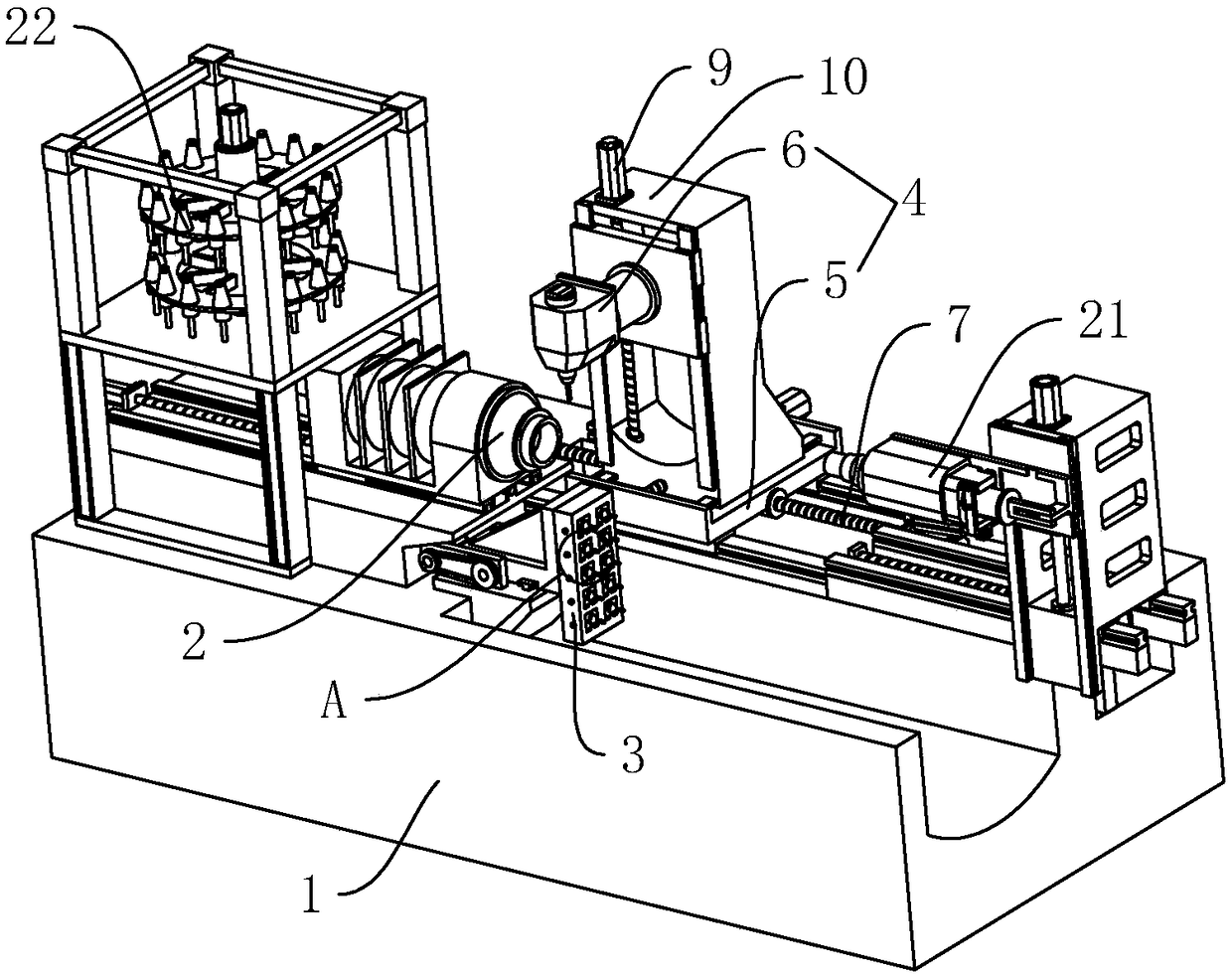
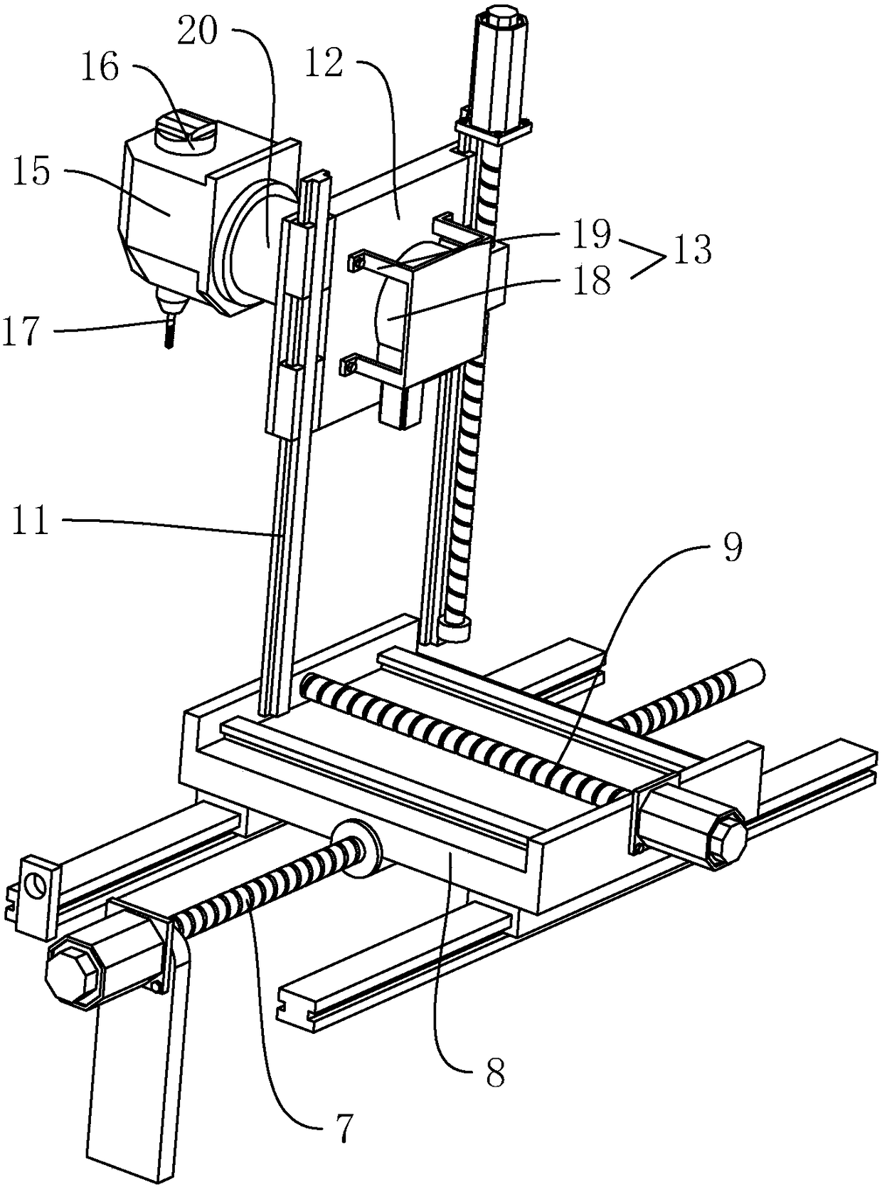
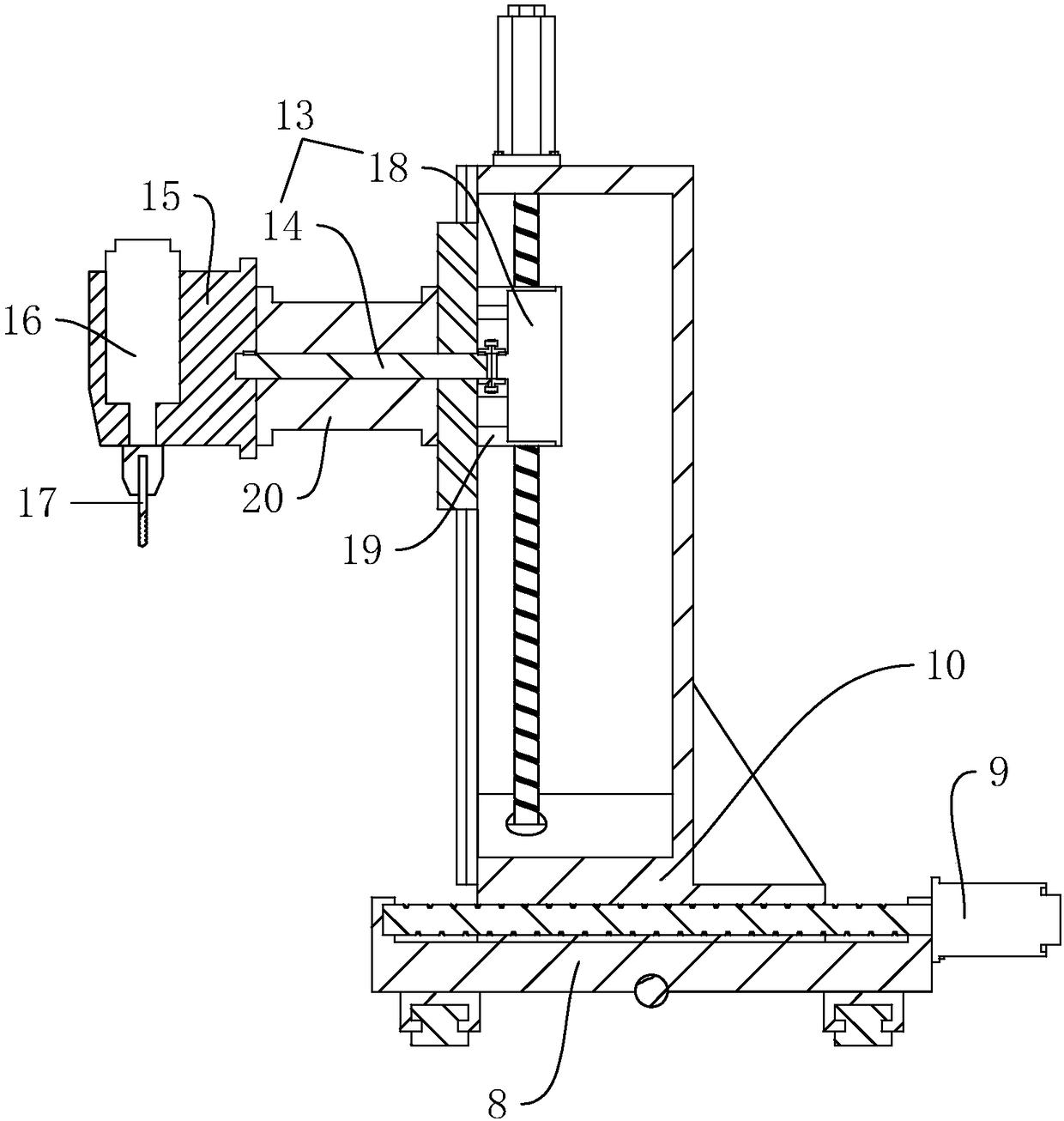
[0035] A high-power turning and milling compound machine tool, such as figure 1As shown, it includes a bed 1 and a main shaft 2 which is slidably arranged on the bed 1 through a screw, and the main shaft 2 can move along its axial direction, and also includes a back tool post 3 which is arranged on one side of the main shaft 2, and which is arranged on the other side of the main shaft 2. The milling device 4 on one side, the milling device 4 includes the drive mechanism 5 that is arranged on the bed 1 and the milling mechanism 6 that is arranged on the drive mechanism 5 in rotation, and the countershaft mechanism 21 is also provided on the bed 1; when the workpiece is processed , the workpiece is first clamped by the spindle 2, and then the driving mechanism 5 drives the milling mechanism 6 to move axially along the spindle 2 to the position correspon...


PUM


Abstract

The invention discloses a large-power turning and milling composite machine tool, belongs to the technical field of machine tools, and aims to solve a problem in a traditional composite machine tool that a milling device is only used for auxiliary machining. The key point of the technical scheme is that the large-power turning and milling composite machine tool comprises a lathe bed, a main shaftinstalled on the lathe bed, a back face knife table installed at one side of the main shaft, and the milling device installed at the other side of the main shaft. The milling device comprises a driving mechanism and a milling mechanism rotatably installed on the driving mechanism. The large-power turning and milling composite machine tool is capable of, through installing the milling device with aB-axis on the lathe bed, and enabling the milling device to be rotated in multiple degrees, completing the milling and machining of a complicated workpiece by cooperating with the main shaft, effectively shortening a product manufacturing process chain, improving production efficiency, reducing a clamping frequency of the workpiece, and effectively improving machining precision, and further has the advantages of reducing floor area, and reducing production cost.

Description

technical field [0001] The invention relates to the technical field of machine tools, more specifically, it relates to a high-power turning-milling compound machine tool. Background technique [0002] A machine tool is a device that mainly uses a turning tool to turn a rotating workpiece. The machine tool is mainly composed of a supporting component, a speed change mechanism, a feed mechanism, a spindle box, and a lubrication system. Most of the traditional machine tools have single functions, some are mainly for turning processing, and some are mainly for milling processing. When it is necessary to perform both turning and milling operations on the workpiece, the workpiece needs to be replaced on a machine tool with different functions for processing. This traditional operation will inevitably lead to too many clamping times of the workpiece, and the corresponding machining accuracy will also be affected. Moreover, due to frequent replacement of the workpiece position, the ...

Claims


Application Information

Patent Timeline
IPC IPC(8): B23P23/02
CPCB23P23/02
Inventor 唐东雷
Owner 津上精密机床(浙江)有限公司
Why Eureka
Try Eureka