Rotor blade tip grinding method

A grinding and rotor technology, applied in the direction of grinding drive device, grinding machine parts, grinding/polishing equipment, etc., can solve the problems of blade tip diameter variation, failure to achieve compression efficiency, failure to achieve working speed, etc. To achieve the effect of ensuring the compression efficiency

Inactive Publication Date: 2018-09-21
HARBIN DONGAN ENGINE GRP
View PDF5 Cites 4 Cited by
  • Summary
  • Abstract
  • Description
  • Claims
  • Application Information

AI Technical Summary

Problems solved by technology

At present, the grinding method of the blade tip is to use an ordinary cylindrical grinder for low-speed grinding. Since the working speed cannot be reached during grinding, affected by the grinding force, the blade shrinks inward during processing. Under high-speed working conditions, the shrinkage When the blade is thrown out, due to the gap between the blade and the tenon and groove

Method used


Image

  • Rotor blade tip grinding method

Examples


Embodiment Construction

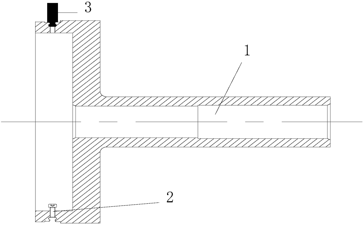
[0013] As shown in the figure, a grinding method of a rotor blade tip includes the following steps:

[0014] (1) design process blisk 1, described process blisk 1 is consistent with the engine blisk external dimension that blade to be ground is installed, and is provided with the tongue and groove of installing blade at the same position as described engine blisk 1, described Radial screws 2 are arranged at the bottom of the mortise groove, and after the blade is installed, the lower end surface of the dovetail groove of the blade is supported; at the same time, a fixed cylindrical pin 3 is arranged along the radial direction at the bottom of the mortise groove, and the cylindrical pin 3 acts on the blade. To the role of circumferential limit;

[0015] (2) Install the blade on the process blisk 1. When installing, ensure that the blade edge plate is close to the cylindrical pin 3, and the orientation of the blade is consistent with the working state;

[0016] (3) Select a uni...


PUM


Abstract

The invention relates to a rotor blade tip grinding method. Through usage of a technology disc, a mortise structure the same with an air compressor rotor is adopted in the technology disc, meanwhile,the manner that the circumferential position of a blade is fixed through a cylinder pin, and a screw tightly jacks the bottom end face of a blade dovetail groove is adopted, the situation that since the rotation speed of a cylindrical grinding machine is low, the grinding force is larger than centrifugal force, the blade is extruded down during blade grinding, working blade stretching is irregular, and the air compression efficiency is influenced is avoided, and the air compressor rotor blade tip diameter value and the bounce value are guaranteed. According to the provided method, it is guaranteed that the diameter value and the bounce value of the machined blade are consistent to the situation during work, and accordingly the air compression efficiency of the air compressor is guaranteed.

Description

technical field [0001] The invention relates to a grinding method, in particular to a rotor blade tip grinding method, which can simulate the grinding of a high-speed rotor blade tip in a low-speed state. Background technique [0002] During the operation of the aero-engine compressor, the gap between the tip of the blade and the outer graphite sealing ring affects the compression efficiency of the compressor. At present, the grinding method of the blade tip is to use an ordinary cylindrical grinder for low-speed grinding. Since the working speed cannot be reached during grinding, affected by the grinding force, the blade shrinks inward during processing. Under high-speed working conditions, the shrinkage When the blade is thrown out, due to the gap between the blade and the tenon and groove where the blade is installed, the diameter of the tip of the blade changes under the action of centrifugal force, and due to the difference in the gap, the diameter changes irregularly, ...

Claims


Application Information

Patent Timeline
IPC IPC(8): B24B1/00B24B19/14B24B47/20
CPCB24B1/00B24B19/14B24B47/20
Inventor 谭贻文吕文生曾桃飞顾志勇于加辉宋秀峰刘昌伟
Owner HARBIN DONGAN ENGINE GRP
Why Eureka
Try Eureka