Circular knife die-cutting machine automatic material receiver

A material catcher and circular knife die technology, which is applied in the mechanical field, can solve the problems that the two materials are not allowed to overlap, frequent material connection, increase the thickness of the material connection position, etc., so as to improve the accuracy and quality of material connection , Reduce production costs and improve production efficiency

Pending Publication Date: 2018-09-21
DONGGUAN LINGYI PRECISION MFG TECH CO LTD
View PDF10 Cites 0 Cited by
  • Summary
  • Abstract
  • Description
  • Claims
  • Application Information

AI Technical Summary

Problems solved by technology

Now the splicing of materials is done manually, the splicing of materials is frequent, the splicing process is complicated, and the production efficiency is affected. If the splicing is not firm, the machine will be re-adjusted or the tool will be damaged.
[0003] Circular knife die-cutting belongs to precision processing, and it is required that the front and rear materials are not allowed to overlap, otherwise the thickness of the material-connecting position will be increased, and the circular knife mold will be damaged during die-cutting, which will not only reduce the service life of the circular knife mold, but also affect the precision of die-cutting

Method used


Image

  • Circular knife die-cutting machine automatic material receiver
  • Circular knife die-cutting machine automatic material receiver
  • Circular knife die-cutting machine automatic material receiver

Examples


Embodiment Construction

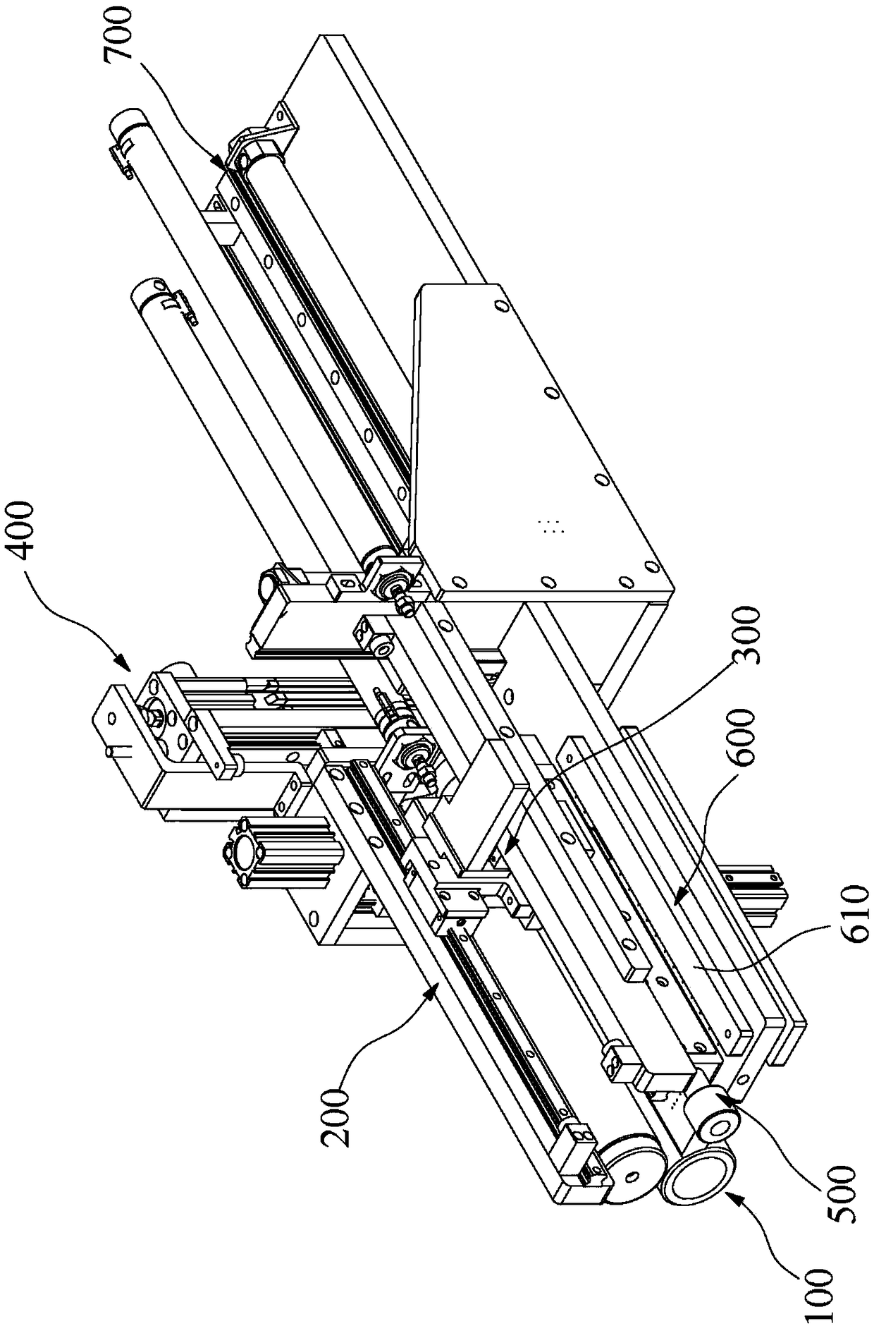
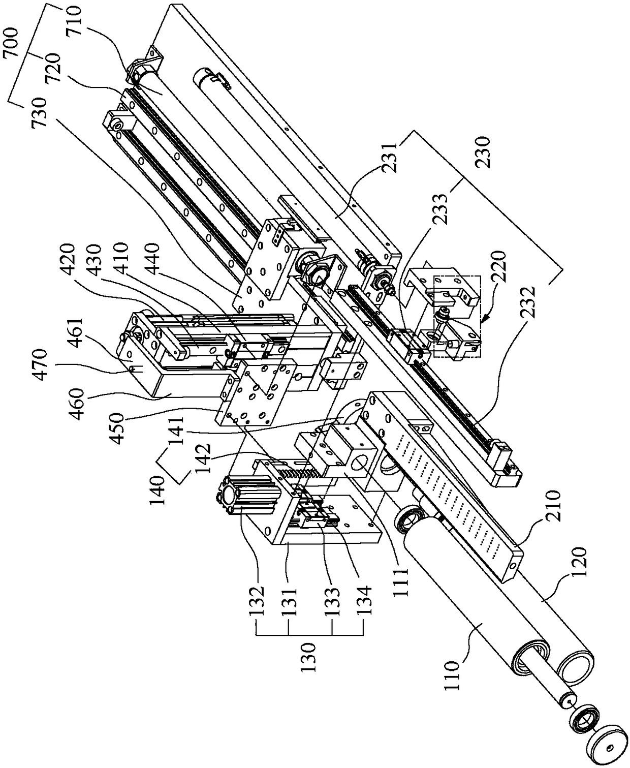
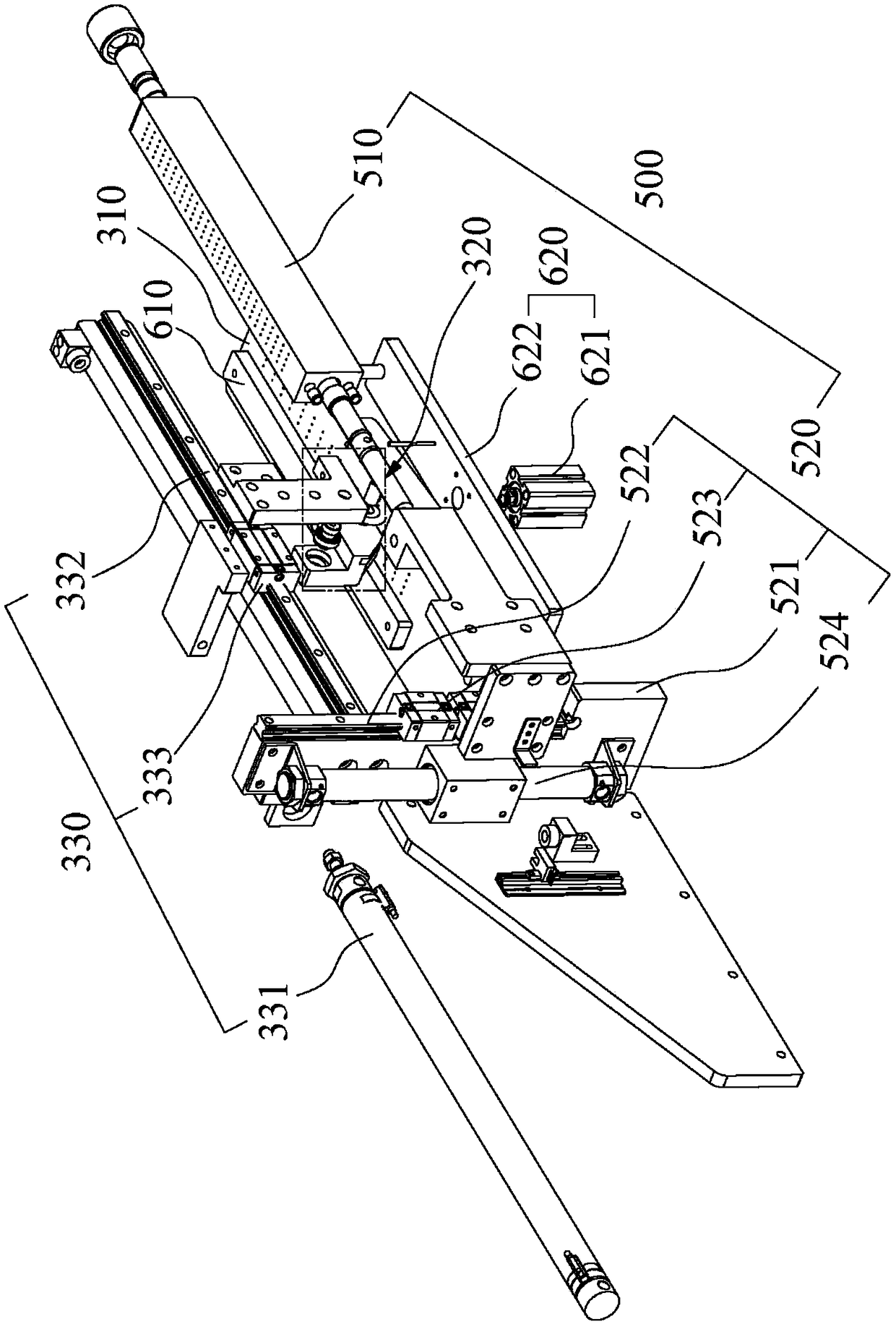
[0030] Attached below Figure 1-7 The present invention is described in further detail.

[0031] According to one aspect of the present invention, an automatic feeder for a circular knife die-cutting machine is provided, and the feeder can connect the spare material tape 800 and the used material tape 900 and stick them together as a whole. like Figure 1-3 As shown, the automatic feeder of the circular knife die-cutting machine in this embodiment includes a feeding mechanism 100, a first cutting mechanism 200, a second cutting mechanism 300, a main lifting mechanism 400, a gluing mechanism 500, and a pressing mechanism 600 and the third driving mechanism 700;

[0032] The feeding mechanism 100 includes an upper roller 110, a lower roller 120, a pressing device 130 for driving the upper roller 110 and the lower roller 120 to compress, and a rotating mechanism 140 for driving one of the upper roller 110 or the lower roller 120 to rotate;

[0033] The first cutting mechanism ...


PUM


Abstract

Provided is a circular knife die-cutting machine automatic material receiver. The circular knife die-cutting machine automatic material receiver comprises a feeding mechanism, a first cutting mechanism, a second cutting mechanism, a main lifting mechanism, a rubberizing mechanism, a material pressing mechanism and a third driving mechanism, wherein the feeding mechanism conveys a standby materialstrap, the first cutting mechanism cuts the end portion of the standby material strap neatly, the second cutting mechanism cuts the end portion of a using material strap neatly, the main lifting mechanism can drive the feeding mechanism and the first cutting mechanism to decline, so that a first cutting knife plate is flush with a second cutting knife plate, the rubberizing mechanism performs rubberizing between the first cutting mechanism and the second cutting mechanism, the material pressing mechanism compresses the use material strap, and the third driving mechanism drives the feeding mechanism and the first cutting mechanism to translate along the direction perpendicular to the movement direction of the material strap. The circular knife die-cutting machine automatic material receiverhas the advantages that non-stop online material receiving can be achieved, the material receiving quality is high, the problems that manual material receiving is frequent and looseness occurs easilyare solved, thereby improving the production efficiency and reducing the production cost.

Description

technical field [0001] The invention relates to the field of mechanical technology, in particular to an automatic feeder for a circular knife die-cutting machine. Background technique [0002] The circular knife die cutting machine is a product that cuts out the desired shape on a continuous strip of material by a rolling circular knife die. In the production process, the length of each small roll of material is limited. After one roll of material is used up, new material needs to be lapped to the end of the previous roll of material to make the production run smoothly. Now the material receiving is done manually, the material receiving is frequent and the material receiving process is complicated, which affects the production efficiency. If the material is not connected firmly, it will lead to machine re-adjustment or tool damage. [0003] Circular knife die-cutting belongs to precision processing, and it is required that the front and rear materials are not allowed to ove...

Claims


Application Information

Patent Timeline
Patent Type & Authority Applications(China)
IPC IPC(8): B26F1/38B26D7/00B65H19/18
CPCB65H19/1805B26D7/00B26F1/38B65H2701/11332
Inventor 周剑
Owner DONGGUAN LINGYI PRECISION MFG TECH CO LTD
Why Eureka
Try Eureka