Ejection mechanism for engine flip injection mold

A technology of injection mold and ejector mechanism, applied in household appliances, other household appliances, applications, etc., can solve problems such as uneven force, adhesion, product surface scratches, etc., to ensure consistent time, avoid uneven height, The effect of preventing damage

Pending Publication Date: 2018-09-21
重庆鼎仁精密模具有限公司
View PDF0 Cites 1 Cited by
  • Summary
  • Abstract
  • Description
  • Claims
  • Application Information

AI Technical Summary

Problems solved by technology

[0003] The ejector rod of the ejector mechanism is located in the chamber. When the product is cooled and formed, there will be adhesion between the ejector rod and the product. When it is manually removed, there may be uneven force, which will cause scratches on the surface of the product.

Method used


Image

  • Ejection mechanism for engine flip injection mold
  • Ejection mechanism for engine flip injection mold
  • Ejection mechanism for engine flip injection mold

Examples


Embodiment Construction

[0025] The following is further described in detail through specific implementation methods:

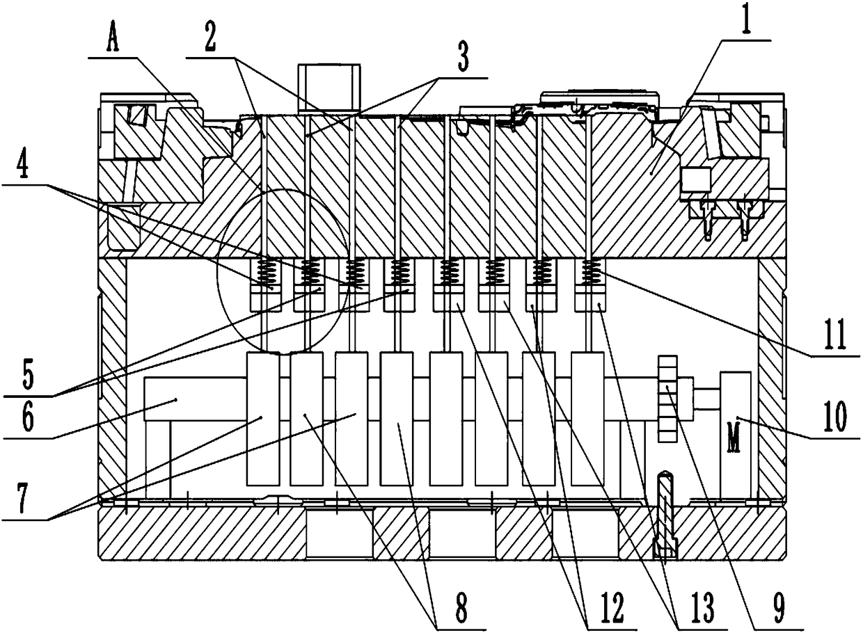
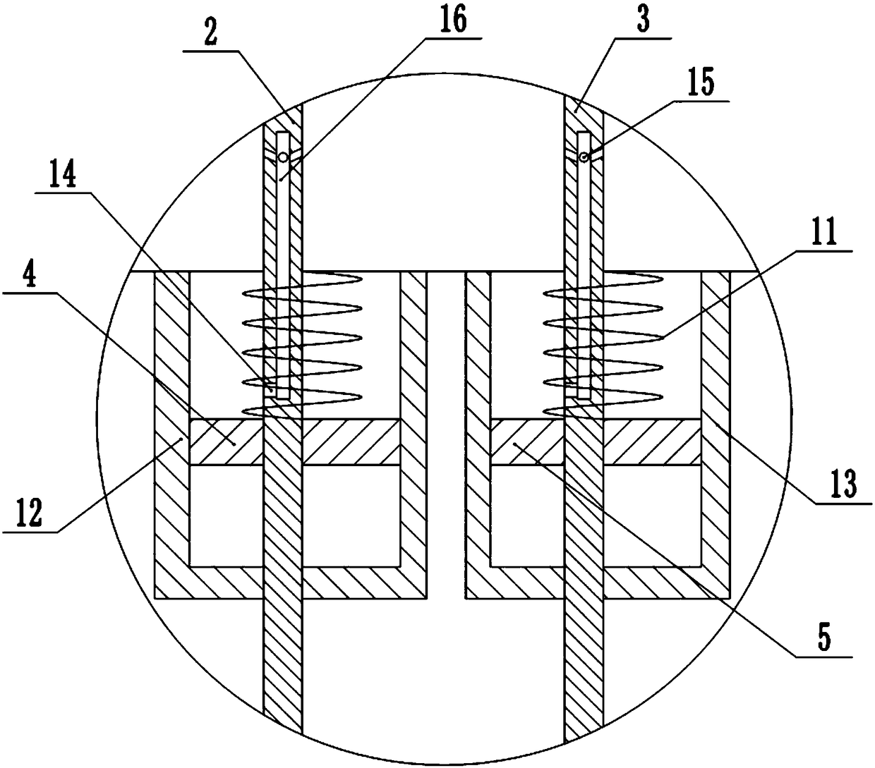
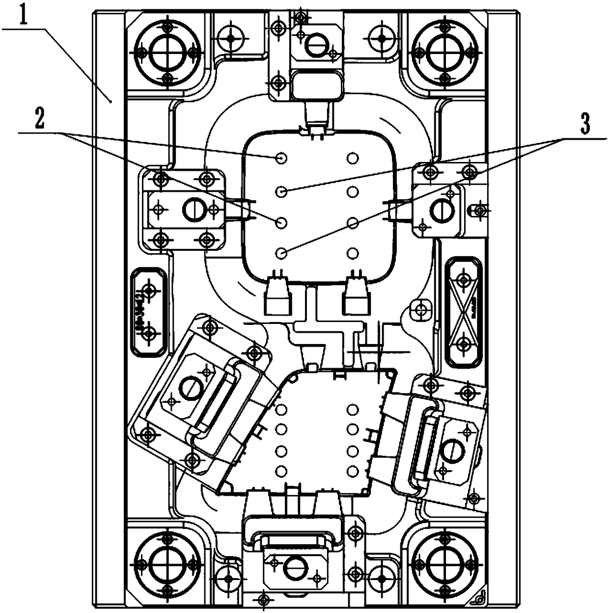
[0026] The reference signs in the drawings of the description include: fixed mold 1, first piston rod 2, second piston rod 3, first piston plate 4, second piston plate 5, rotating shaft 6, first cam 7, second cam 8 , gear 9, motor 10, return spring 11, first cylinder 12, second cylinder 13, air inlet 14, air outlet 15, pipeline 16.

[0027] The embodiment is basically as attached figure 1 , figure 2 and image 3 Shown: The ejection mechanism used for the injection mold of the engine clamshell includes four horizontal rotating shafts 6 arranged between the fixed mold 1 and the base, and the rotating shafts 6 are parallel to each other.

[0028] like Figure 4 As shown: a group of first cams 7 are distributed on the rotating shaft 6; second cams 8 are arranged between adjacent first cams 7, and the line connecting the rotation center of the first cam 7 and the second cam 8 to the ...


PUM


Abstract

The invention belongs to the field of injection molds and in particular discloses an ejection mechanism for an engine flip injection mold. The ejection mechanism comprises a plurality of rotary shaftswhich are horizontally arranged and are arranged between a fixed mold and a base, wherein the rotary shafts are parallel to each other; one group of first cams are distributed on the rotary shafts; second cams are arranged between the adjacent first cams; air cylinders are arranged above the first cams and the second cams; cylinder bodies of the air cylinders are fixed on the lower surface of thefixed mold; piston rods of the air cylinders penetrate through piston plates and the cylinder bodies; the piston rods abut against the corresponding the cams respectively; resetting springs are arranged between the cylinder bodies of the air cylinders and the piston plates; the piston rods are provided with air inlet holes; the piston rods are provided with two inclined and upward air outlet holes in a directly facing manner; pipes are arranged in the piston rods and are used for communicating air outlet holes and the air inlet holes; gears which are mutually engaged are arranged at the leftends of the rotary shafts. The ejection mechanism for the engine flip injection mold, disclosed by the invention, aims at solving the sticking problem between an ejection rod and a product.

Description

technical field [0001] The invention belongs to the field of injection molds, and specifically discloses an ejection mechanism for an injection mold for an engine cover. Background technique [0002] Injection mold is a molding mold widely used in the production of plastic parts, and it is also a tool to give plastic products a complete structure and precise dimensions. Injection molding is a processing method used in mass production of certain complex-shaped parts. The injection mold consists of two parts, the movable mold and the fixed mold. The movable mold is installed on the movable template of the injection molding machine, and the fixed mold is installed on the fixed template of the injection molding machine. During injection molding, the movable mold and the fixed mold are closed to form a gating system and a cavity, and the hot-melted plastic is injected into the cavity through the gating system, and the required product is formed after cooling and molding. When th...

Claims


Application Information

Patent Timeline
Patent Type & Authority Applications(China)
IPC IPC(8): B29C45/40
CPCB29C45/4005B29L2031/749
Inventor 李建军
Owner 重庆鼎仁精密模具有限公司
Why Eureka
Try Eureka