Bridge support base

A bridge support and support seat technology, applied in bridges, bridge parts, bridge construction, etc., can solve the problems of beam end expansion and damage, energy consumption, energy waste, etc., to achieve convenient disassembly, energy saving, and convenient replacement Effect

Active Publication Date: 2018-09-21
丰泽智能装备股份有限公司 +1
View PDF6 Cites 4 Cited by
  • Summary
  • Abstract
  • Description
  • Claims
  • Application Information

AI Technical Summary

Problems solved by technology

During the process of raising the beam body, the damage to the upper structure of the beam body is very large. For example, if the train track is partially raised, it is easy to cause accidents such as rollover for high-speed trains. Therefore, when replacing the bridge support, it is necessary to break the bridge The construction will affect the normal use of the road and cause huge economic losses due to road breakage; moreover, the construction technology of the jacking beam body is difficult, because the bridge cannot withstand the jacking up of one end, so the entire beam body needs to be jacked up as a whole , which is technically unrealizable for larger continuous girder bridges; not only is it easy to cause telescopic damage at the end of the girder during the jacking process, but it will also consume a lot of energy and waste energy
The existing bridge bearing replacement method takes a long time, is technically difficult, and causes great damage to the beam body and auxiliary structures, and cannot meet the needs of super large bridges and bridge bearing replacement without interrupting traffic

Method used


Image

  • Bridge support base
  • Bridge support base
  • Bridge support base

Examples


Embodiment Construction

[0036] In order to make the object, technical solution and advantages of the present invention clearer, the present invention will be described in further detail below in conjunction with specific embodiments and with reference to the accompanying drawings. Wherein the same components are denoted by the same reference numerals. It should be noted that the words "front", "rear", "left", "right", "upper" and "lower" used in the following description refer to directions in the drawings. The terms "inner" and "outer" are used to refer to directions toward or away from, respectively, the geometric center of a particular component.

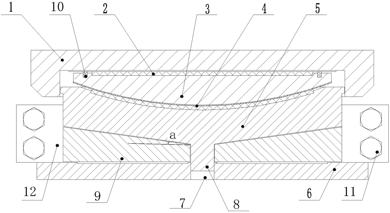
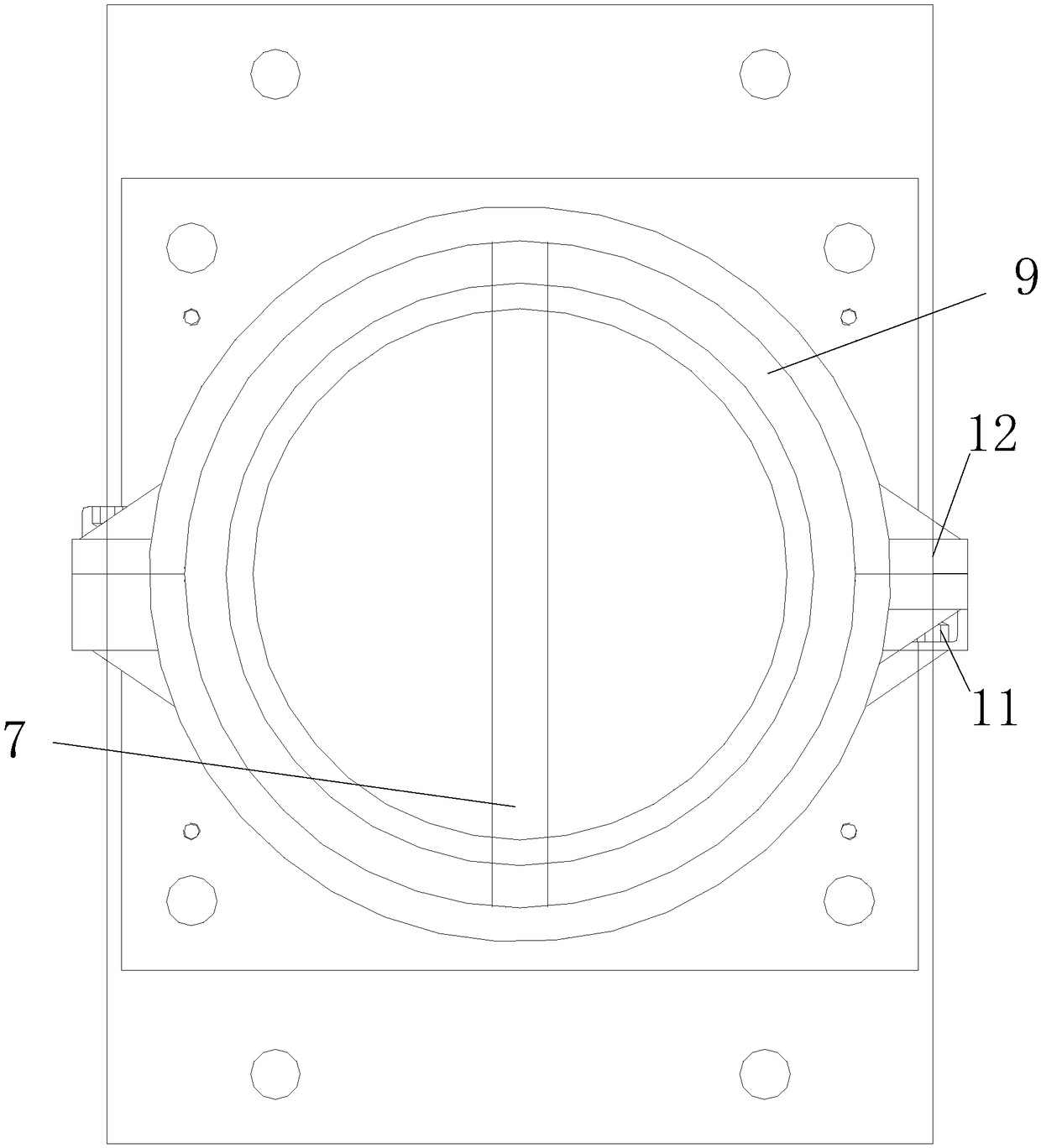
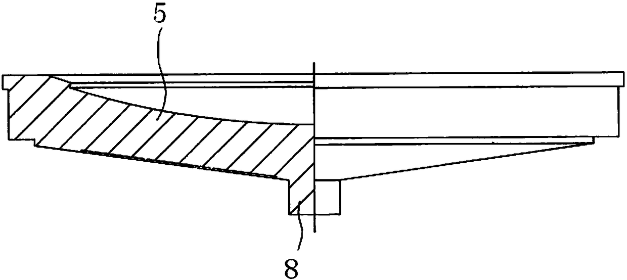
[0037] figure 1 It is a cross-sectional view of the bridge support used in the specific embodiment of the present invention along the width direction of the beam body. figure 2 for figure 1 The schematic diagram of the connection state between the limit body of the bridge support and the installation base is shown. image 3 for figure 1 The partia...


PUM


Abstract

The invention discloses a bridge support base. The bridge support base comprises a support base body, a mounting base, at least two limiting bodies and a clamping ring; the top of the support base body is used for supporting a beam body, the bottom of the support base body is inclined downwards from the edge to the center, an included angle is formed by extension lines of the end face of the bottom of the support base body and the plane where the top of the support base body is located, and a limiting insertion piece extends from the middle of the bottom of the support base body; the mountingbase is opposite to the support base body, a mounting cavity is formed between the mounting base and the support base body in the circumferential direction of the limiting insertion piece, and the mounting base is provided with a limiting groove used in cooperation with the limiting insertion piece; the limiting bodies are evenly distributed in the mounting cavity, can abut against the limiting insertion piece, and are used for providing fitting support for the bottom of the support base body; the clamping ring is arranged between the support base body and the mounting base and used for limiting the limiting bodies into the mounting cavity or releasing the limiting bodies from the mounting cavity. The bridge support base is convenient to replace and short in consumed time, and the replacement can be completed without traffic blockage.

Description

technical field [0001] The invention relates to the technical field of road-rail bridges, and more specifically, to a bridge support. Background technique [0002] In recent years, with the increase of investment in infrastructure construction, the construction of road-rail bridge projects has developed rapidly. In the process of bridge construction, the beam body and the bridge pier are connected as a whole through the bridge support, and the bridge support has been widely used. [0003] The bridge support in the prior art includes an upper support body, a plane slide plate, a steel liner assembly, a spherical slide plate and a lower support body from top to bottom, and the plane slide plate makes the upper support body and the lower support body produce a small The horizontal displacement of the spherical slide makes the bridge bearing rotate slightly. Steel liner assemblies are used to increase the overall strength of bridge bearings. Since the bridge support needs to ...

Claims


Application Information

Patent Timeline
IPC IPC(8): E01D19/04
CPCE01D19/048
Inventor 李承根徐瑞祥李炯高日李晓明韩文涛张亚军王晶王洪强刘展
Owner 丰泽智能装备股份有限公司
Why Eureka
Try Eureka