System and method for treating engine exhaust gas

An exhaust gas treatment and engine technology, which is applied to combustion engines, engine components, machines/engines, etc., can solve problems such as loss of exhaust resistance, low muffler performance, and reduced energy utilization, so as to avoid exhaust resistance and flow Smooth and reduce exhaust drag effect

Active Publication Date: 2020-03-20
湖南七度动力科技有限公司
View PDF9 Cites 3 Cited by
  • Summary
  • Abstract
  • Description
  • Claims
  • Application Information

AI Technical Summary

Problems solved by technology

[0002] The exhaust gas of the engine contains a large amount of gas impact kinetic energy, which is often not utilized by existing exhaust devices, or the exhaust resistance will be lost during the utilization process;
[0003] At the same time, in the north of the severe cold region, due to the low ambient temperature, the engine will inhale a large amount of cold air during the intake stroke, and the combustion chamber needs to increase additional heat to heat the cold air, which reduces energy efficiency; the muffler is As an important part of the engine, the existing muffler has low noise reduction performance. To improve its noise reduction performance, it is necessary to increase the volume of the muffler to make up for it, which creates a new problem of occupying space

Method used


Image

  • System and method for treating engine exhaust gas
  • System and method for treating engine exhaust gas
  • System and method for treating engine exhaust gas

Examples


Embodiment Construction

[0035] The present invention will be further described below in conjunction with the accompanying drawings.

[0036] 1. Structure description:

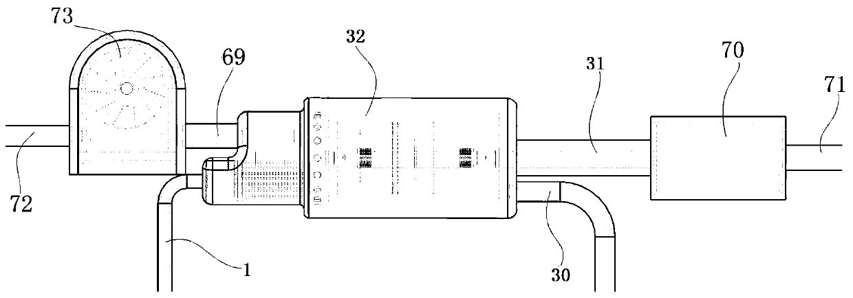
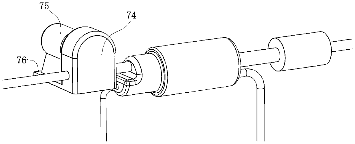
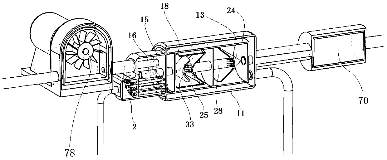
[0037] as attached Figures 1 to 3 The engine exhaust treatment system shown includes an exhaust kinetic energy generating unit 73, a noise reduction and air preheating unit 32, an exhaust purification unit 70, an engine exhaust exhaust pipe 72, an exhaust kinetic energy generating unit exhaust pipe 15, and an air preheating unit. Intake pipe 30, air preheating outlet pipe 1, muffler exhaust pipe 31, exhaust gas purification unit exhaust pipe 71;

[0038] The exhaust gas exhaust pipe 72 of the engine is connected to the tail gas intake end of the kinetic energy generating unit 73, and the exhaust end of the kinetic energy generating unit 73 is connected to the exhaust pipe 15 of the kinetic energy generating unit. The air outlet end of the unit exhaust pipe 15 is connected to the exhaust gas inlet end of the noise reduction and air ...


PUM


Abstract

The invention discloses an engine exhaust treatment system. The engine exhaust treatment system comprises an exhaust kinetic energy generation unit, a muffler and air preheating unit, an exhaust purification unit and an engine exhaust tailpipe. The engine exhaust tailpipe is connected with the exhaust inlet end of the exhaust kinetic energy generation unit, the exhaust end of the exhaust kinetic energy generation unit is connected with an exhaust kinetic energy generation unit exhaust pipe, the exhaust end of the exhaust kinetic energy generation unit exhaust pipe is connected with the exhaustinlet end of the muffler and air preheating unit, and the exhaust outlet end of the muffler and air preheating unit is connected with a muffler tailpipe. The engine exhaust treatment system is simplein structure, the generation unit is provided with a gas channel to enable the exhaust to flow smoothly in a shell cavity, generation is performed under the premise that exhaust resistance is greatlyreduced, and the disadvantage of increasing the exhaust resistance is avoided.

Description

technical field [0001] The invention belongs to the field of tail gas treatment, in particular to an engine tail gas treatment system and a method thereof. Background technique [0002] The exhaust gas of the engine contains a large amount of gas impact kinetic energy, which is often not utilized by existing exhaust devices, or the exhaust resistance will be lost during the utilization process; [0003] At the same time, in the north of the severe cold region, due to the low ambient temperature, the engine will inhale a large amount of cold air during the intake stroke, and the combustion chamber needs to increase additional heat to heat the cold air, which reduces energy efficiency; the muffler is An important part of the engine, the existing muffler has low noise reduction performance. To improve the noise reduction performance, it is necessary to increase the volume of the silencer to make up for it, and this has caused a new problem of occupying space. Contents of the ...

Claims


Application Information

Patent Timeline
Patent Type & Authority Patents(China)
IPC IPC(8): F01N5/04F01N5/02F01N1/10F01N13/08
CPCF01N1/089F01N1/10F01N5/02F01N5/04F01N13/08Y02T10/12
Inventor 唐天庆
Owner 湖南七度动力科技有限公司
Why Eureka
Try Eureka