Automatic butted pipe joint device

An automatic docking and pipe joint technology, applied in the direction of pipe/pipe joint/pipe fitting, valve device, connection with fluid cut-off device, etc., to achieve the effect of high degree of automation, improved accuracy and small pressure drop

Inactive Publication Date: 2018-09-21
XIAN UNIV OF TECH
View PDF7 Cites 12 Cited by
  • Summary
  • Abstract
  • Description
  • Claims
  • Application Information

AI Technical Summary

Problems solved by technology

In addition, manual operations have very large limitations in small spaces, high altitudes, high temperatures, and toxic environments.

Method used


Image

  • Automatic butted pipe joint device
  • Automatic butted pipe joint device
  • Automatic butted pipe joint device

Examples


Embodiment Construction

[0030] The present invention will be described in detail below in conjunction with the accompanying drawings and specific embodiments.

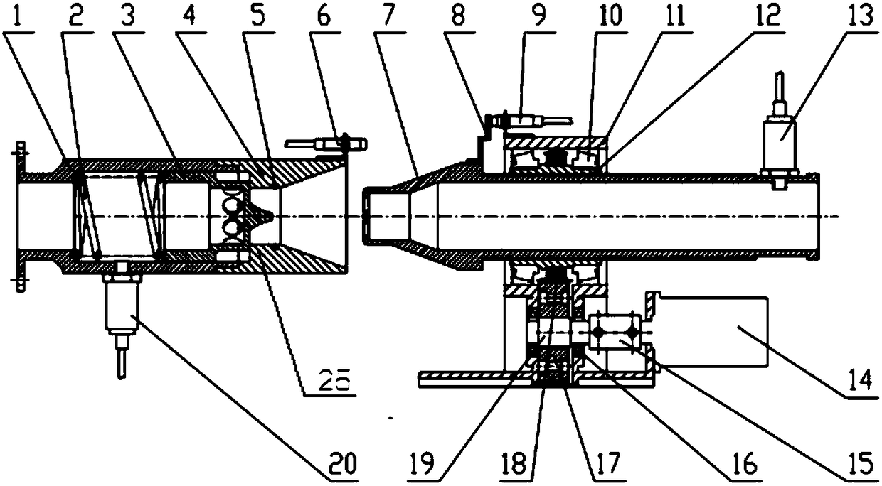
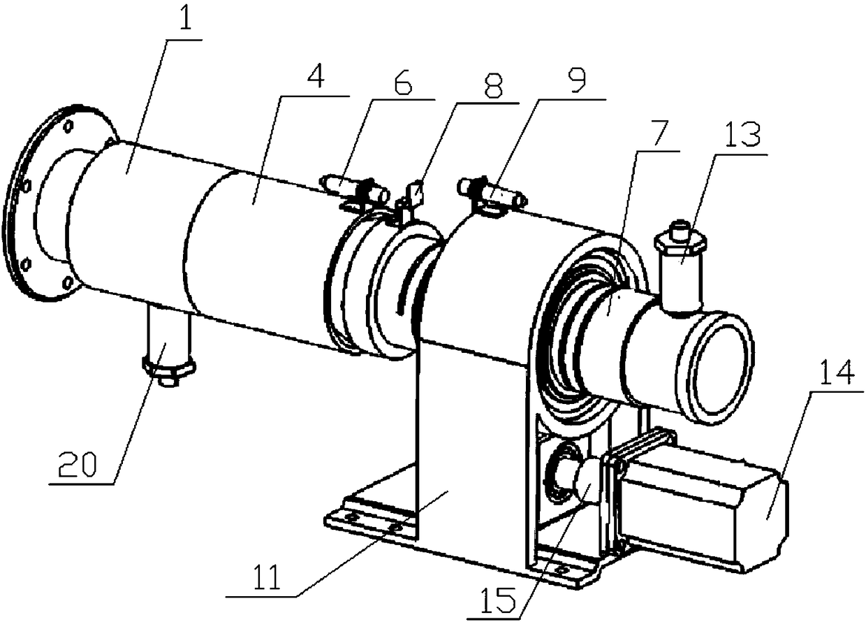
[0031] A pipe joint device for automatic docking of the present invention, such as figure 1 and figure 2 As shown, it includes a fixed sleeve 1 and a tapered guide sleeve 4 connected by threads, the tapered guide sleeve 4 is butted with a tapered butt joint 7, and the outside of the tapered butt joint 7 is threaded with a nut 12 to form a For the screw pair, the nut 12 is fixed. When the nut 12 rotates, the conical butt joint 7 can be driven to move in the axial direction. The nut 12 is externally connected with the driven gear 18, and the nut 12 is located at both ends of the driven gear 18 and is also sleeved with conical rollers. The sub-bearing 10, the tapered roller bearing 10 is connected with the base 11, and also includes a driving mechanism, the driving mechanism is connected to the gear shaft 19 through the coupling 15, the gear s...


PUM


Abstract

The invention discloses an automatic butted pipe joint device and belongs to the technical field of pipeline connecting auxiliary equipment. A cone-shaped butt joint is controlled by a driving mechanism to be butted with a cone-shaped guide sleeve automatically, so that the automatic butted pipe joint device is high in degree of automation and wide in application range, and can be used at a high pressure. A valve element is of a bell-shaped hood structure, a plurality of round holes are formed radially, and the sum of areas of all holes is greater than that of the section of the valve element,so that a runner is steady to transit, and therefore, when the valve element is opened, water flows from the valve element, and the valve is small in pressure drop, small in impact and high in flow capacity. Pressure sensors are mounted on a fixed sleeve and the cone-shaped butt joint for detecting the pressure of the pipeline in real time. When the pressure in the pipeline is abnormal, connection is disenabled, so that the equipment or the pipeline is prevented from being damaged; and the butting automation of the pipe joint can be achieved.

Description

technical field [0001] The invention belongs to the technical field of pipeline connection auxiliary equipment, and in particular relates to an automatic butt joint pipe joint device. Background technique [0002] Pipe joints are the most commonly used parts in the field of machinery industry. In the pipelines that need to be disassembled frequently in the field of hydraulic and pneumatic technology, pipe joints can realize quick disconnection and connection between pipelines. However, the existing quick joints press steel balls through the jacket Fall into the V-shaped groove of the joint body to connect the two joint bodies. When disassembling, it is necessary to use a spring to pull the outer cover back, so as to drive the steel ball to move out of the V-shaped groove, and then pull out the joint body. Although a certain connection effect can be achieved, this type of quick connector is manually operated, and the plugging resistance of the connector is relatively large, ...

Claims


Application Information

Patent Timeline
Patent Type & Authority Applications(China)
IPC IPC(8): F16L29/02F16K1/36F17D5/00
CPCF16K1/36F16L29/02F17D5/00
Inventor 高峰张晗李艳张旭涛王琰段继豪
Owner XIAN UNIV OF TECH
Why Eureka
Try Eureka