Exploring device for shaft or deep hole

A detection device and shaft technology, applied in the direction of optical device exploration, measurement, borehole/well components, etc., can solve problems such as the inability to determine the occurrence of surrounding rock, limited cable transmission distance, and affect theoretical analysis work, etc., to achieve continuous and real-time The effect of downhole detection

Pending Publication Date: 2018-09-21
NORTHWEST UNIV
View PDF0 Cites 2 Cited by
  • Summary
  • Abstract
  • Description
  • Claims
  • Application Information

AI Technical Summary

Problems solved by technology

The previous process practice experience shows that the existing downhole camera detection technology mainly uses cables to transmit signals, but the transmission distance of cables is limited, only 50m to 100m, and the signal attenuates with the depth of lowering; the exploration well may have a certain degree of inclination, and the downhole camera During the process, the camera rotates downhole, and the specific position of the well wall cannot be determined through the captured pictures, so the occurrence of the surrounding rock cannot be determined, which will have a great impact on the collected data, thus affecting the subsequent theoretical analysis work

Method used


Image

  • Exploring device for shaft or deep hole
  • Exploring device for shaft or deep hole
  • Exploring device for shaft or deep hole

Examples


Embodiment Construction

[0017] A specific embodiment of the present invention will be described in detail below in conjunction with the accompanying drawings, but it should be understood that the protection scope of the present invention is not limited by the specific embodiment.

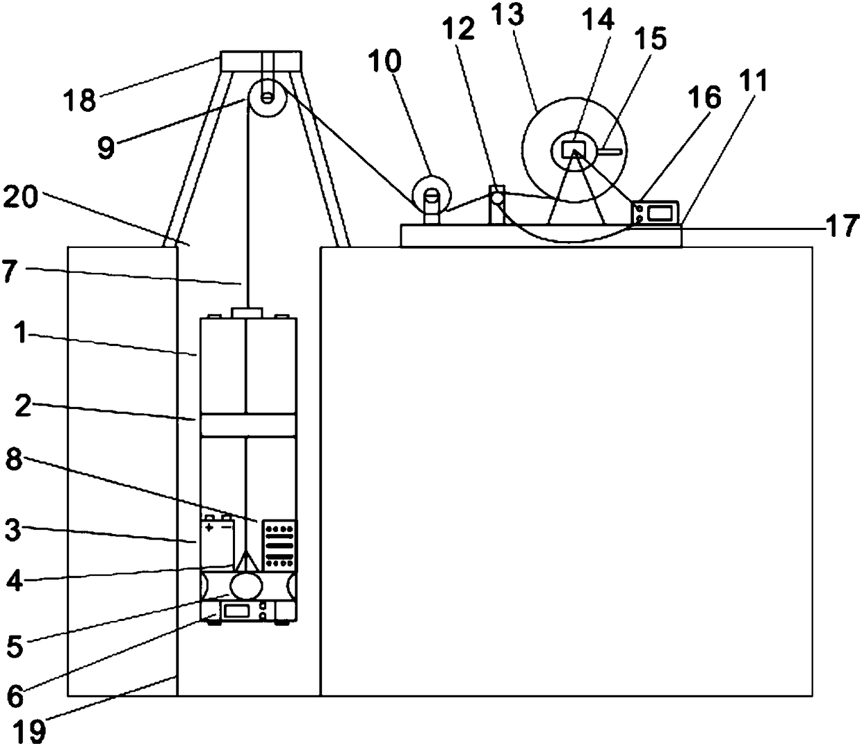
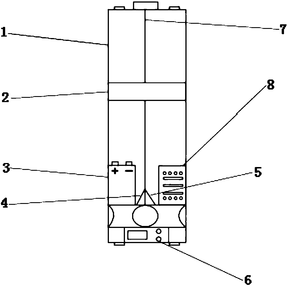
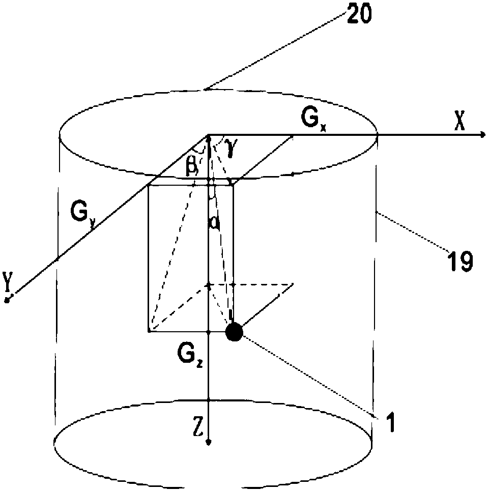
[0018] Such as Figure 1-5 As shown, the embodiment of the present invention provides a detection device for shafts or deep holes, including a detection tube 1, the detection tube 1 is arranged in the wellhead 20, the wellhead 20 is provided with a tripod 18, and the tripod 18 is provided with a pulley a9 , the pulley a9 is wound with an optical fiber 7; the right side of the wellhead 20 is provided with a base 11, and the base 11 is provided with a pulley b10, an encoder 12, a pay-off wheel 13 and a data acquisition device 16 in sequence from left to right; the detection tube 1 is located at In the shaft, the bottom of the detection tube 1 is provided with a laser rangefinder 6, and the detection tube 1 is also provided w...


PUM

PropertyMeasurementUnit
Lengthaaaaaaaaaa

Abstract

The invention discloses an exploring device for a shaft or deep hole. The exploring device comprises an exploring tube, the exploring tube is located in the shaft, the bottom of the exploring tube isprovided with a laser distance measuring instrument, and an angle sensor and an infrared camera are arranged on the exploring tube; the inner portion of the exploring tube is provided with an LED modulator tube, the angle sensor, the infrared camera and the laser distance measuring instrument are respectively connected with an input end of a photoelectric conversion board through wires, and an output end of the photoelectric conversion board is connected with one end of an optical fiber; the other end of the optical fiber is connected with a data acquisition device through a pulley b and a pay-off wheel in sequence; the device can solve the problems that the distance of cable transmitting signal is short and radio cannot transmit signals under water through the optical fiber; the angle sensor can record rotation angles at any time, an encoder records the displacement length of optical fiber lowering, the laser distance measuring instrument records the horizontal distance between the exploring tube and the well wall, a specific position of a shooting picture is determined, the rotation problem during lowering is solved, and downhole exploring can be continuously carried out in realtime.

Description

technical field [0001] The invention relates to the technical field of detecting the surrounding rock stability of a shaft or a deep hole, in particular to a detection device for a shaft or a deep hole. Background technique [0002] With the vigorous development of my country's infrastructure construction, mining, water conservancy, and civil engineering. The underground engineering involved in all aspects of transportation is facing severe safety problems, and is attracting more and more attention. The past process practice experience shows that the existing downhole camera detection technology mainly uses cables to transmit signals, but the transmission distance of cables is limited, only 50m to 100m, and the signal attenuates with the depth of lowering; the exploration well may have a certain degree of inclination, and the downhole camera During the process, the camera was rotating downhole, and the specific position of the well wall and the occurrence of the surrounding...

Claims


Application Information

Patent Timeline
IPC IPC(8): G01V8/10E21B23/00E21B47/00E21B47/12
CPCE21B23/00E21B47/12G01V8/10E21B47/002
Inventor 谷天峰王家鼎王晨兴许元珺孔嘉旭孙彬
Owner NORTHWEST UNIV
Why Eureka
Try Eureka