Terminal equipment multi-antenna system and terminal equipment signal transmission method

A multi-antenna system and terminal equipment technology, applied to antennas, antenna components, specific array feeding systems, etc., can solve the problem that the antenna cannot transmit signals, etc., and achieve the effect of solving the inability to transmit signals and avoiding signal interruption

Inactive Publication Date: 2017-12-15
ZTE CORP
View PDF12 Cites 6 Cited by
  • Summary
  • Abstract
  • Description
  • Claims
  • Application Information

AI Technical Summary

Problems solved by technology

[0004] Embodiments of the present invention provide a terminal device multi-antenna system and a terminal device signal transmission method, to at least solve the problem in the related art that the antenna of the terminal device cannot transmit signals due to the influence of the human body

Method used


Image

  • Terminal equipment multi-antenna system and terminal equipment signal transmission method
  • Terminal equipment multi-antenna system and terminal equipment signal transmission method
  • Terminal equipment multi-antenna system and terminal equipment signal transmission method

Examples


Embodiment 1

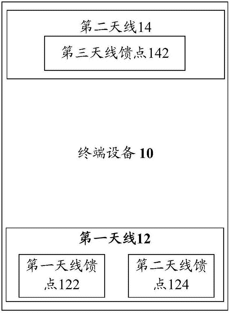
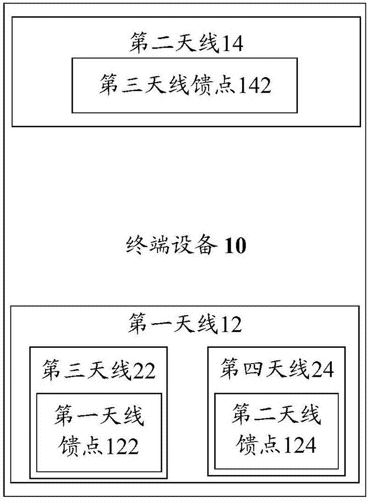
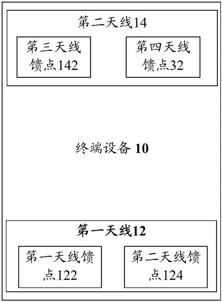
[0030] This embodiment also provides a terminal device multi-antenna system. figure 1 is a structural frame of a terminal equipment multi-antenna system according to an embodiment of the present invention Figure 1 ,Such as figure 1 As shown, the system includes: a first antenna 12 and a second antenna 14, wherein,

[0031] The first antenna 12 is arranged at the bottom of the terminal device 10, and the second antenna 14 is arranged at the top of the terminal device 10;

[0032] The first antenna 14 includes: a first antenna feed point 122 and a second antenna feed point 124, the first antenna feed point 122 is used to transmit mobile communication signals of the first frequency band, and the second antenna feed point 124 is used for for transmitting mobile communication signals in the second frequency band;

[0033]The second antenna 14 includes: a third antenna feed point 142 , and the third antenna feed point 142 is used to transmit mobile communication signals in all m...

Embodiment 2

[0044] The method embodiment provided in Embodiment 2 of the present application may be executed in a mobile terminal, a computer terminal, or a similar computing device. Taking running on a mobile terminal as an example, Figure 4 It is a hardware structural block diagram of a mobile terminal of a terminal equipment signal transmission method according to an embodiment of the present invention, as shown in Figure 4 As shown, the mobile terminal 40 may include one or more (only one is shown in the figure) processor 402 (the processor 402 may include but not limited to a processing device such as a microprocessor MCU or a programmable logic device FPGA, etc.), for A memory 404 for storing data, and a transmission device 406 for communication functions. Those of ordinary skill in the art can understand that, Figure 4 The shown structure is only for illustration, and it does not limit the structure of the above-mentioned electronic device. For example, mobile terminal 40 may...

Embodiment 3

[0079] This embodiment also provides a terminal equipment signal transmission device, which is used to implement the above embodiments and preferred implementation modes, and what has already been described will not be repeated. As used below, the term "module" may be a combination of software and / or hardware that realizes a predetermined function. Although the devices described in the following embodiments are preferably implemented in software, implementations in hardware, or a combination of software and hardware are also possible and contemplated.

[0080] Figure 9 is a structural block diagram of a terminal equipment signal transmission device according to an embodiment of the present invention, such as Figure 9 As shown, the device includes:

[0081] The first determination module 92 is configured to determine a target antenna feed point whose mobile communication signal strength satisfies a preset condition among the first antenna feed point, the second antenna feed...


PUM


Abstract

The invention provides a terminal equipment multi-antenna system and a terminal equipment signal transmission method. The terminal equipment multi-antenna system comprises a first antenna and a second antenna. The first antenna is arranged at the bottom part of terminal equipment, and the second antenna is arranged at the top part of the terminal equipment. The first antenna comprises a first antenna feed point and a second antenna feed point, wherein the first antenna feed point is used for transmitting a mobile communication signal of a first frequency band, and the second antenna feed point is used for transmitting a mobile communication signal of a second frequency band. The second antenna comprises a third antenna feed point, wherein the third antenna feed point is used for transmitting mobile communication signals of all mobile communication signal frequency bands within the coverage of the terminal equipment. The terminal equipment multi-antenna system and the terminal equipment signal transmission method solve the problem in the prior art that signal transmission fails due to the effect of the human body on antennas of the terminal equipment, thereby avoiding signal interruption caused by the effect of the human body on the antenna of the terminal equipment.

Description

technical field [0001] The present invention relates to the communication field, in particular, to a terminal equipment multi-antenna system and a terminal equipment signal transmission method. Background technique [0002] Most of the current terminal mobile phones are mobile phones with all-metal back covers or metal frames. The antennas of these two types of mobile phones are basically directly realized by using metal appearance. One of the disadvantages of using metal as an antenna is that it is greatly affected by the human body. When the mobile phone is held in hand, or in the scene where people hold the mobile phone and put it to the ear to answer the phone (hereinafter referred to as the head-and-hand scene), the signal (antenna performance) will drop very seriously, and even cause signal interruption. [0003] There is currently no effective solution to the problem in the related art that the antenna of the terminal device cannot transmit signals due to the influen...

Claims


Application Information

Patent Timeline
Patent Type & Authority Applications(China)
IPC IPC(8): H01Q1/24H01Q1/50H01Q5/50H01Q21/30
CPCH01Q1/243H01Q5/50H01Q21/0006H01Q21/30H01Q1/24H01Q1/50
Inventor 唐菊
Owner ZTE CORP
Why Eureka
Try Eureka