3D display component

A display component and 3D technology, applied in the field of 3D display, can solve the problems of small depth of field and low viewing freedom of super multi-viewpoint display technology, and achieve the effect of increasing depth of field, enhancing 3D display effect, and increasing viewing freedom.

Inactive Publication Date: 2018-09-21
ZHANGJIAGANG KANGDE XIN OPTRONICS MATERIAL
View PDF6 Cites 8 Cited by
  • Summary
  • Abstract
  • Description
  • Claims
  • Application Information

AI Technical Summary

Problems solved by technology

[0008] The main purpose of this application is to provide a 3D display component to solve the problem that the viewing f...

Method used


Image

  • 3D display component
  • 3D display component
  • 3D display component

Examples


Embodiment 1

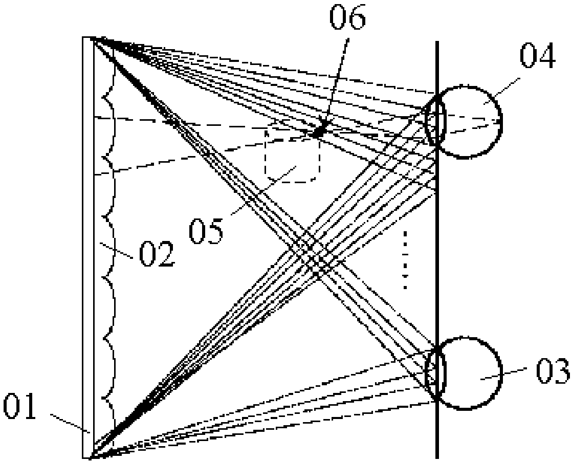
[0081] The structure of the display component and the light path diagram are as follows Figure 8 As shown, wherein, the display unit is an LCD panel, and its specific structure is as follows Figure 5 Shown; The spatial light modulator includes three modulation modules, each modulation module is a lens array, and each lens array includes a plurality of cylindrical lenses arranged at intervals, see Figure 6 Shown; the visual separation unit is a cylindrical mirror array structure.

[0082] The three modulation modules of the spatial light modulation unit modulate the light emitted by the three pixel groups in the display unit to three predetermined areas, that is, three virtual display screens, and the light emitted by the three virtual display screens is modulated by the visual separation unit After, such as Figure 8 As shown, three visible areas are respectively reached, and the three visible areas are respectively the first visible area 100 , the second visible area 200...

Embodiment 2

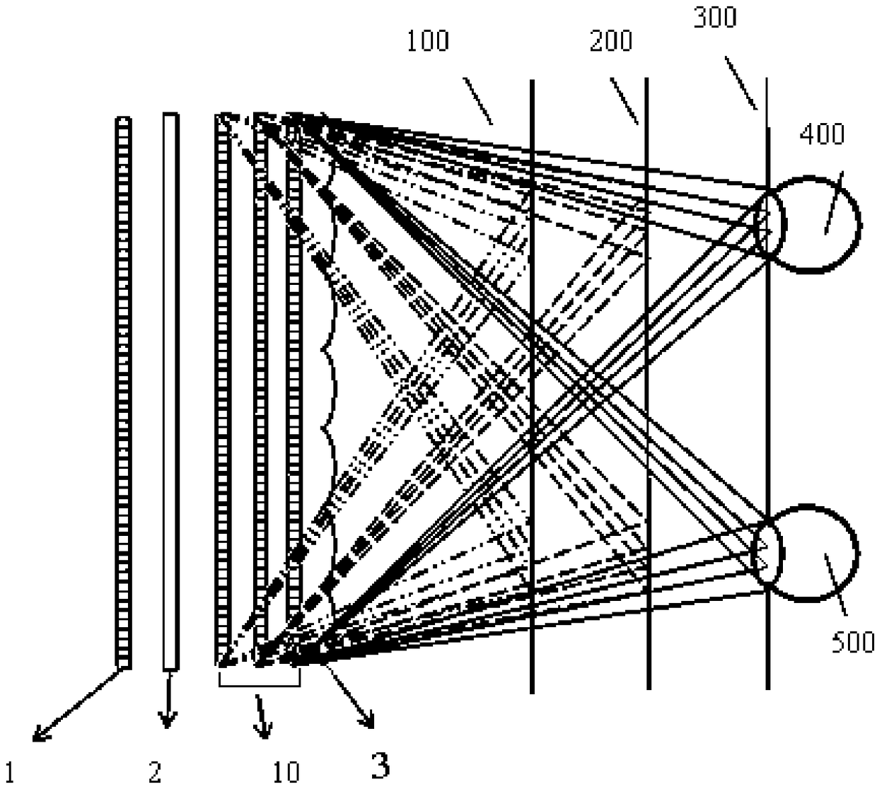
[0090] The difference from Embodiment 1 is that the modulation module in the spatial light modulation unit is a modulation module with a switchable mode, that is, a modulation module with adjustable refractive index, and the three modulation modules use time division multiplexing technology to combine the three pixels in the display unit The light emitted by the group is modulated into more predetermined areas (more than 3 predetermined areas), such as Figure 9 As shown, the viewing freedom in the vertical direction (in the direction perpendicular to the display surface) can be further increased.

Embodiment 3

[0092] The difference from Embodiment 1 is that the visual separation unit is a visual separation unit with adjustable refractive index, that is, the cylindrical lens array structure is adjustable in refractive index, and the visual separation unit utilizes time division multiplexing technology to combine three virtual display screens The image of the image is modulated into more visual areas (greater than 3 visual areas), such as Figure 10 As shown, the degree of viewing freedom in the vertical direction (in the direction perpendicular to the display surface) can be further increased, which is convenient for multiple people to watch.


PUM


Abstract

The invention provides a 3D display component. The 3D display component comprises a display unit which comprises at least two pixel groups, wherein each pixel group comprises multiple pixel rows and each pixel row comprises multiple sub-pixels which are arranged in turn in a spaced way; a spatial light modulation unit which is arranged on one side of the display unit, wherein the spatial light modulation unit uses the modulation module to modulate the light emitted by multiple pixel groups to different preset areas, each preset area is arranged on one side away from the display unit of the spatial light modulation unit, the preset areas corresponding to at least two pixel groups are not overlapped in the first direction, and the first direction is the direction pointing to the spatial light modulation unit from the display unit; and a visual separation unit which is arranged on one side away from the display unit of the spatial light modulation unit, wherein each preset area is arranged between the visual separation unit and the spatial light modulation unit. According to the 3D display component, the viewing degree of freedom can be enhanced and the depth of field can be increased.

Description

technical field [0001] The present application relates to the field of 3D display, in particular, to a 3D display component. Background technique [0002] Traditional 3D display technology causes visual fatigue due to lack of sufficient depth cues. People usually perceive depth information through four factors: convergence, binocular parallax, motion parallax, and focus. [0003] Traditional 3D display technologies include glasses-type binocular parallax display, naked-eye binocular parallax display and multi-viewpoint display. Due to insufficient motion parallax, these display technologies cannot achieve real 3D viewing effects. [0004] Traditional 3D display technology produces 3D display effects by forming different parallax images in the left and right eyes of people. When human eyes watch 3D images, the focus (accomodation) depth produced by lens adjustment is always fixed on the display screen, while the eye The depth of convergence (vergence) generated by the exter...

Claims


Application Information

Patent Timeline
IPC IPC(8): G02B27/22G02B30/27
CPCG02B30/27
Inventor 吴雪梅薛翰聪王晓雷
Owner ZHANGJIAGANG KANGDE XIN OPTRONICS MATERIAL
Why Eureka
Try Eureka