Wireless energy transmission method and structure

A technology of wireless energy transmission and microstructure, applied in the direction of transformers, electrical components, inductors, etc., can solve the problems of inability to guarantee power transmission and uniform magnetic field, and achieve uniform transmission power, large range, and expanded application range Effect

Pending Publication Date: 2018-09-21
ZHEJIANG UNIV
View PDF0 Cites 2 Cited by
  • Summary
  • Abstract
  • Description
  • Claims
  • Application Information

AI Technical Summary

Problems solved by technology

Although they can all increase the system power, in the process of electromagnetic coupling transmission, there...

Method used


Image

  • Wireless energy transmission method and structure
  • Wireless energy transmission method and structure
  • Wireless energy transmission method and structure

Examples


Embodiment 1

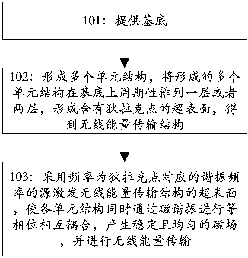
[0048] According to an embodiment of the present invention, a wireless energy transmission method is provided, such as figure 1 shown, including:

[0049] Step 101: providing a base;

[0050] According to the embodiment of the present invention, the type of material of the substrate can be selected according to requirements; preferably, in this embodiment, the substrate is a material with a relative permittivity of 2.55, such as polytetrafluoroethylene.

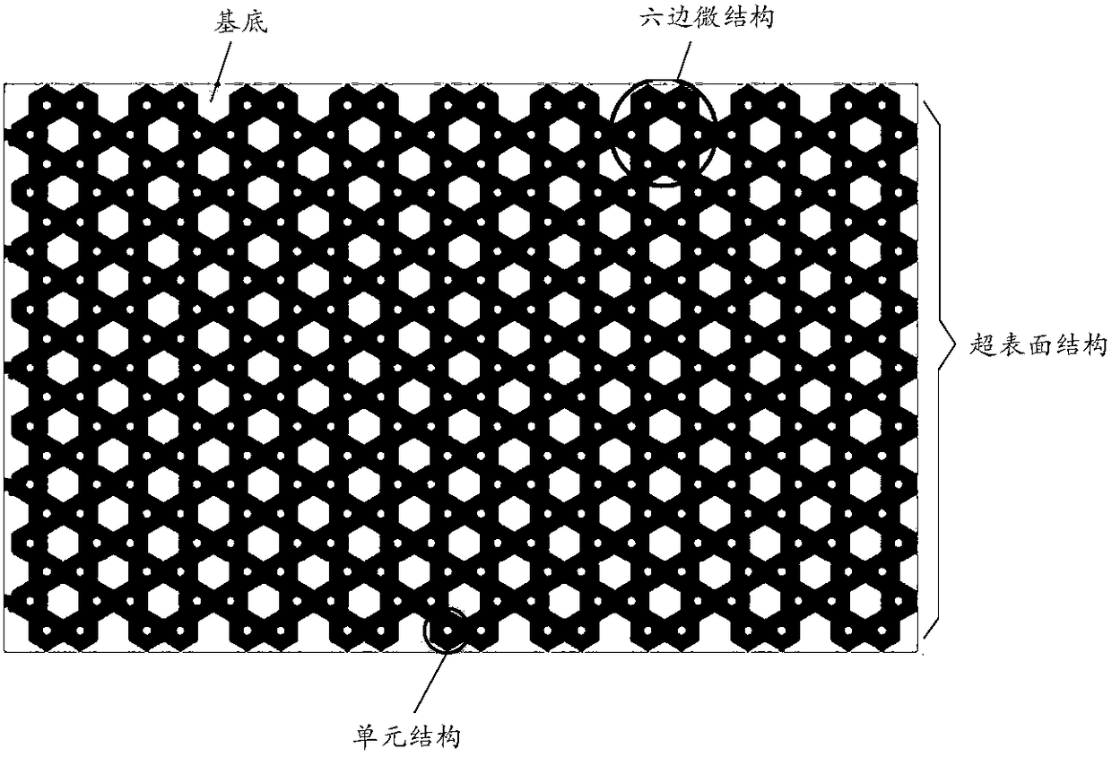
[0051] Step 102: forming multiple unit structures, periodically arranging one or two layers of the formed multiple unit structures on the substrate to form a metasurface containing Dirac points to obtain a wireless energy transmission structure;

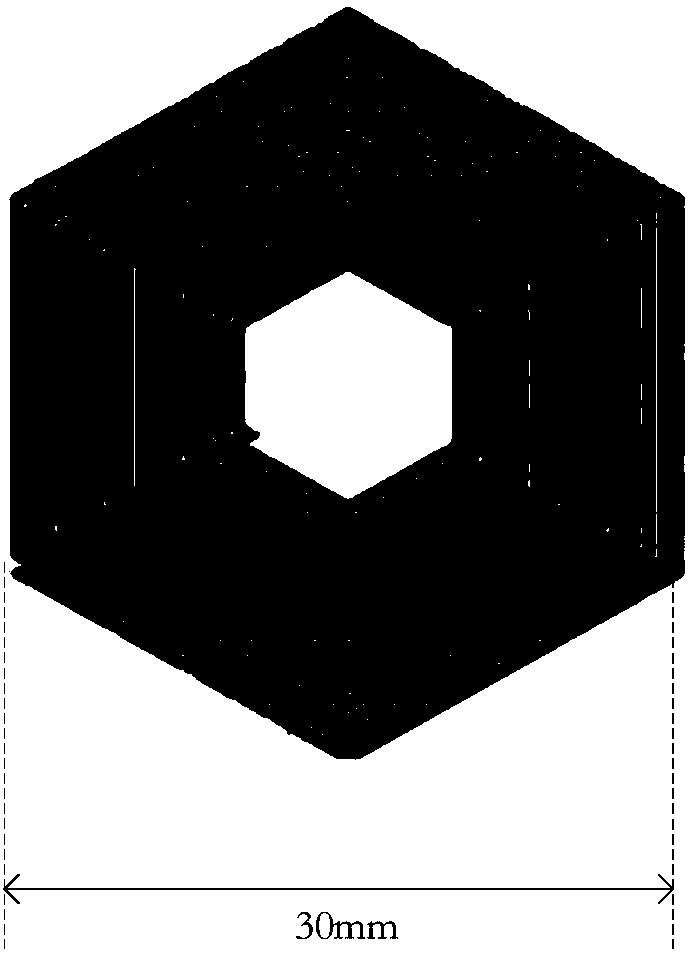
[0052] In the present invention, forming a plurality of unit structures is specifically: performing multiple windings on a plurality of unconnected metal wires respectively to form a corresponding central hollow hexagon to obtain a plurality of unit structures;

[0053] Wherein, t...

Embodiment 2

[0070] According to an embodiment of the present invention, a wireless energy transmission structure applicable to the method described in Embodiment 1 is provided, including:

[0071] base;

[0072] A metasurface formed on a substrate; the metasurface includes one or two layers of periodically arranged unit structures formed with Dirac points.

[0073] According to the embodiment of the present invention, the unit structure is specifically a hexagon with a hollow center formed by multiple windings of a metal wire that is not connected at the end;

[0074] In this embodiment, the metal wire is specifically a conductive metal wire, such as aluminum wire, iron wire, etc.; the width of the metal wire, the number of winding turns, and the interval between the coils formed by winding can be set according to requirements For example, in the present embodiment, the width of metal wire is 0.4mm, and the number of winding turns is 15 circles, and the interval between the coils formed ...


PUM

PropertyMeasurementUnit
Widthaaaaaaaaaa

Abstract

The invention discloses a wireless energy transmission method and a structure and belongs to the technical field of wireless energy transmission. The method comprises the following steps: providing asubstrate; forming a plurality of unit structures, periodically arranging the plurality of formed unit structures on the substrate on one layer or two layers, and forming a metasurface containing Dirac points, so as to obtain a wireless energy transmission structure; exciting the metasurface of the wireless energy transmission structure by adopting a source of which the frequency is a resonant frequency corresponding to the Dirac points, enabling the various unit structures to simultaneously perform constant phase inter-coupling through magnetic resonance, generating a stable and uniform magnetic field, and performing wireless energy transmission. According to the wireless energy transmission method disclosed by the invention, the wireless energy transmission structure containing the Diracpoints is formed, and the metasurface of the wireless energy transmission structure is excited by adopting the source of which the frequency is the resonant frequency corresponding to the Dirac points, so that the uniform and stable magnetic field is generated, the wireless energy can be transmitted at a uniform transmission power, and the transmission is long in distance and wide in range.

Description

technical field [0001] The present invention relates to the technical field of wireless energy transmission, in particular to a wireless energy transmission method and structure. Background technique [0002] In the traditional power supply system, wires have been used as a medium for efficient energy transmission, which makes our life and work more and more convenient. However, due to people's increasing material needs, the working environment of electronic equipment is becoming more and more complex, especially in harsh environments such as flammable and explosive, the wired power supply network is easily damaged and many potential safety hazards arise; at the same time, the wired power supply network There are also problems such as poor equipment mobility, unsightly visual environment, and exposed power supply; and in areas such as oceanic islands and remote deep forests, it is difficult to use wired transmission energy for construction and high maintenance costs. Theref...

Claims


Application Information

Patent Timeline
IPC IPC(8): H02J50/12H02J50/40H01F38/14
CPCH02J50/12H02J50/40H01F38/14
Inventor 杨怡豪王婵王华萍皇甫江涛
Owner ZHEJIANG UNIV
Why Eureka
Try Eureka