
Surgery assisting device used in cardiothoracic surgery department

A technology of surgical operation and auxiliary device, which is applied in the direction of surgery, surgical equipment, medical science, etc., can solve the problems of inconvenient and easy-to-fatigue operation, and achieve the effect of reducing fatigue

Inactive Publication Date: 2018-09-25
王荣华
View PDF13 Cites 4 Cited by
  • Summary
  • Abstract
  • Description
  • Claims
  • Application Information

AI Technical Summary

Problems solved by technology

During the working process, assistants or nurses are needed to assist the doctor and help the doctor to complete the operation. During the operation, various medical devices are required to be used, and most of them are passed on to the doctor by the nurse for use. After the doctor finishes using them, the nurse will recycle the medical device , but during the doctor's operation, the doctor works for a long time and is prone to fatigue and inconvenient operation. Therefore, an auxiliary device is needed to cooperate with the doctor's operation to facilitate the doctor's operation and reduce the doctor's work intensity

Method used


Image

  • Surgery assisting device used in cardiothoracic surgery department
  • Surgery assisting device used in cardiothoracic surgery department
  • Surgery assisting device used in cardiothoracic surgery department

Examples


Embodiment 1

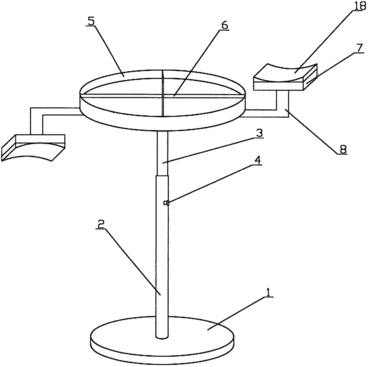
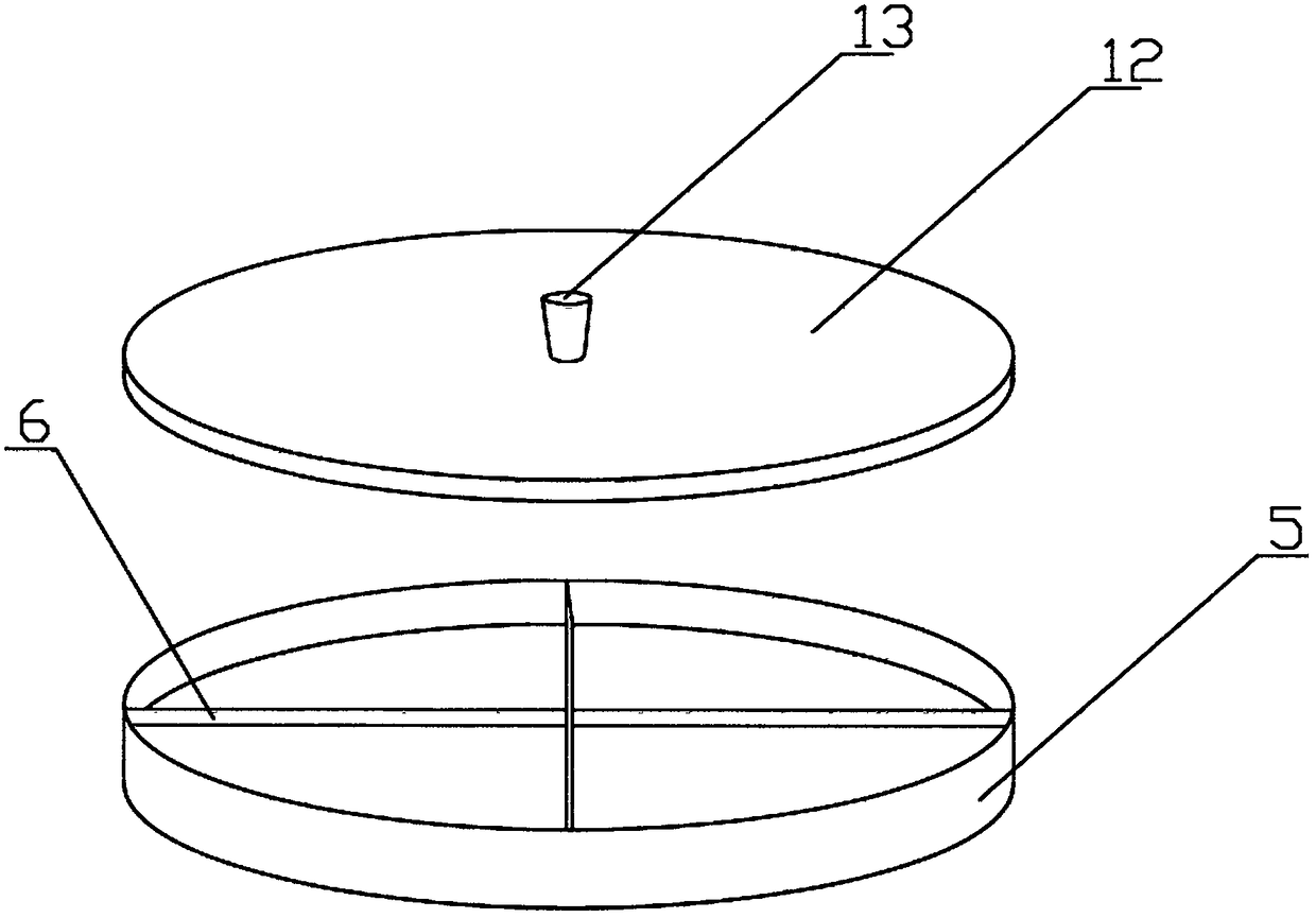
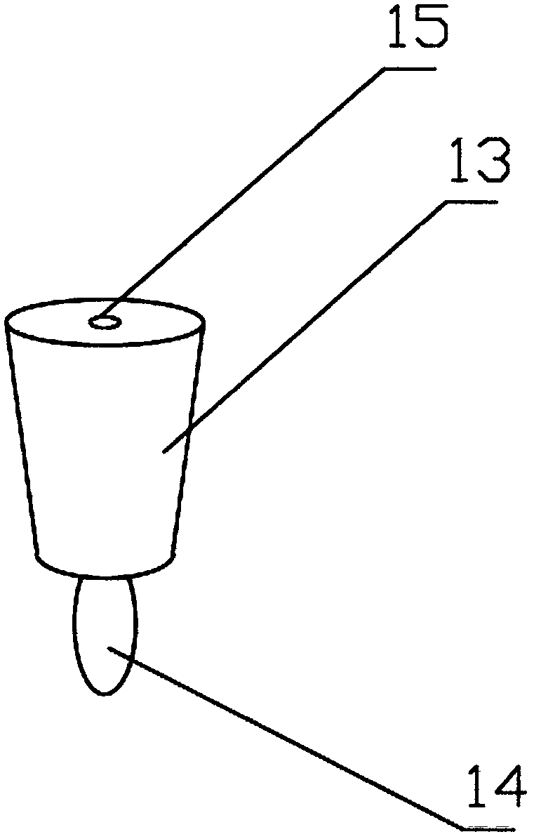
[0025] Such as figure 1 , figure 2 , image 3 and Figure 4 As shown, an auxiliary device for cardiothoracic surgery includes a base 1, on which the base 1 is provided with a lifting support rod, the lifting support rod includes an outer sleeve 2 and a telescopic rod 3, the bottom of the outer sleeve 2 is fixedly connected with the base 1, and the base 1 A screw hole is provided in the middle, and an internal thread is provided in the screw hole, and an external thread matched with the internal thread is provided at the bottom of the outer casing 2, and the outer casing 2 is connected with the base 1 through the thread. The lifting support rod and the base are connected by threads, which is convenient for disassembly. When not in use, the lifting support rod can be disassembled for convenient storage and movement.

[0026] The telescopic rod 3 is inserted into the outer sleeve 2 and can move up and down along the outer sleeve 2. The outer sleeve 2 is provided with fastenin...

Embodiment 2

[0032] Such as figure 2 , image 3 , Figure 5 ,and Figure 6 As shown, the difference between this embodiment and Embodiment 1 is that the lifting support rod is an electric push rod 16 , the bottom of the electric push rod 16 is fixedly connected to the base 1 , and the top of the electric push rod 16 is rotatably connected to the tray 5 . Electric push rod 16 can carry out automatic up and down telescopic adjustment, and control is convenient.

[0033] A storage battery is arranged in the base 1, and the storage battery is connected with the electric push rod 16. The base 1 is provided with a control button 17, and the control button includes a power button, an up button and a down button. The electric push rod is a new type of electric actuator. The electric push rod is a new type of linear actuator mainly composed of a motor, a push rod and a control device, which can realize remote control and centralized control. The electric push rod makes reciprocating motion wit...


PUM


Abstract

The invention discloses a surgery assisting device used in the cardiothoracic surgery department. The surgery assisting device comprises a base, wherein a lifting supporting rod is arranged on the base, the bottom of the lifting supporting rod is fixedly connected with the base, the top of the lifting supporting rod is in rotary connection with a tray, partition plates are arranged in the tray anddivide the tray into multiple storage spaces, and an arm bracket is arranged on the side wall of the tray. The lifting supporting rod can perform lifting, the height of the tray can be adjusted, thetray is in rotary connection with the lifting supporting rod, multiple storage spaces separated by the partition plates are arranged in the tray, and different medical instruments can be stored. The tray can rotate, tray rotation as required is facilitated, the arm bracket on the tray can support the arm of a doctor after the doctor works for a long time, and fatigue of the doctor is relieved.

Description

technical field [0001] The invention relates to the technical field of medical equipment, in particular to an auxiliary device for cardiothoracic surgery. Background technique [0002] Cardiothoracic surgery is a very delicate work. During the operation, doctors need to concentrate on working wholeheartedly, and no mistakes are allowed. During the working process, assistants or nurses are needed to assist the doctor and help the doctor to complete the operation. During the operation, various medical devices are required to be used, and most of them are passed on to the doctor by the nurse for use. After the doctor finishes using them, the nurse will recycle the medical device , but in the doctor's operation process, the doctor works for a long time, and is prone to fatigue and inconvenient operation. Therefore, an auxiliary device is needed to cooperate with the doctor's operation to facilitate the doctor's operation and reduce the doctor's work intensity. Contents of the ...

Claims


Application Information

Patent Timeline
IPC IPC(8): A61B50/33A61B90/60
CPCA61B50/33A61B90/60
Inventor 王荣华田志菊李辉
Owner 王荣华
Learn More