Nozzle cleaning device and nozzle cleaning method

A technology for cleaning devices and nozzles, applied in cleaning methods and utensils, spraying devices, chemical instruments and methods, etc., can solve the problems of removal of components that cannot be wiped, lack of treated objects, etc., and achieves the effect of reducing the area and improving the removal efficiency.

Active Publication Date: 2018-09-25
DAINIPPON SCREEN MTG CO LTD
View PDF10 Cites 0 Cited by
  • Summary
  • Abstract
  • Description
  • Claims
  • Application Information

AI Technical Summary

Problems solved by technology

In addition, since this residue remains in a position not in contact with the wiping member, it cannot be properly removed by movement of the wiping member
Moreover, if the residue falls on the object to be processed, it will still cause defects in the object to be processed.

Method used


Image

  • Nozzle cleaning device and nozzle cleaning method
  • Nozzle cleaning device and nozzle cleaning method
  • Nozzle cleaning device and nozzle cleaning method

Examples


Embodiment Construction

[0060] Hereinafter, embodiments of the present invention will be described in detail with reference to the drawings.

[0061]

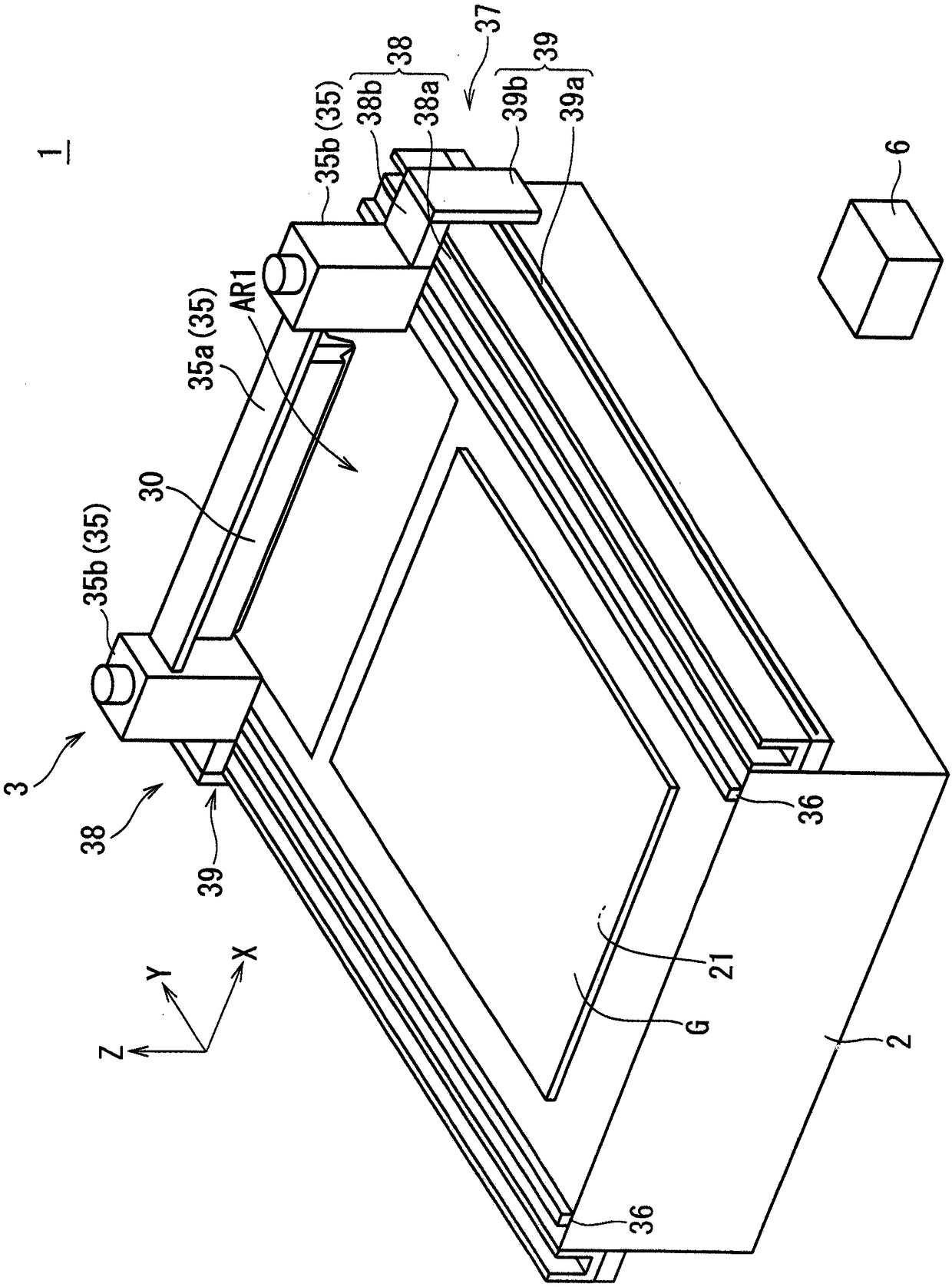
[0062] figure 1 It is a perspective view schematically showing an example of the structure of the coating apparatus 1 of embodiment. Also, for clarity of direction, in figure 1 The XYZ Cartesian coordinate system in which the Z direction is the vertical direction and the XY plane is the horizontal plane is appropriately indicated in each of the following figures. In addition, the size and number of each part are exaggerated or simplified as necessary for easy understanding. In addition, descriptions of "+X-axis side" and "-X-axis side" are appropriately introduced in the following description. "+X-axis side" means one side in the X direction, and "-X-axis side" means the other side in the X direction. The same is true for other coordinate axes. In addition, "+Z axis side" means the upper side of Z direction.

[0063] The coating device 1 of th...


PUM


Abstract

Provided is a nozzle cleaning device capable of more appropriately reducing the amount of deposits remaining on the side surface of a slit nozzle. The nozzle cleaning device includes an abutting member, a cleaning liquid storage tank, and a nozzle elevating means. While abutting the lower region of the outer surface of the nozzle, the abutting member moves in the horizontal direction along the outer surface and scrapes off deposits adhering to the lower region. The upper portion of the cleaning liquid storage tank is open, and the cleaning liquid is stored as a stored cleaning liquid. The nozzle elevating means reciprocates the nozzle moved above the cleaning liquid storage tank between a lower position (P11) and an upper position (P21). The lower position (P11) is a position where the upper region above the lower region is in contact with the stored cleaning liquid and the upper position (P22) is a position higher than the lower position (P11).

Description

technical field [0001] The invention relates to a nozzle cleaning device and a nozzle cleaning method. Background technique [0002] Conventionally, it is known that, in the state where a coating liquid is sprayed from a slit nozzle having an elongated discharge port, the slit nozzle is moved relative to a target object such as a base material or a substrate to coat the object to be processed. Apparatus for applying coating liquid (slit coater). The discharge port is formed on the lower end surface of the slit nozzle. [0003] In the slit coater, if a uniform spraying state of the coating liquid is formed over the entire length of the slit-shaped discharge port, a coating film with a uniform film thickness can be formed on the object to be processed. On the other hand, if there are deposits such as residues produced due to the drying and solidification of the coating liquid in a part of the above-mentioned discharge port, it will not be possible to form a uniform spray sta...

Claims


Application Information

Patent Timeline
Patent Type & Authority Applications(China)
IPC IPC(8): B05B15/555B05B15/68B05B15/20B05B14/00B08B7/04
CPCB08B7/04
Inventor 安陪裕滋
Owner DAINIPPON SCREEN MTG CO LTD
Why Eureka
Try Eureka