imaging device

An imaging device and imaging technology, used in instruments, equipment for electrical recording technology using charge patterns, optics, etc.

Active Publication Date: 2020-12-08
CANON KK
View PDF13 Cites 0 Cited by
  • Summary
  • Abstract
  • Description
  • Claims
  • Application Information

AI Technical Summary

Problems solved by technology

[0004] However, for this structure, there is room for improvement in properly removing the generated particles

Method used


Image

  • imaging device
  • imaging device
  • imaging device

Examples


Embodiment 1

[0037] (1) Overall structure of the imaging device

[0038] Before describing the characteristic part of this embodiment, the general structure of the image forming apparatus will be described. Figure 4 is a diagram showing the structure of the imaging device. Figure 12 is a block diagram showing the relationship between the control circuit and the various components. The printer 1 forms an image at an image forming portion using an electrophotographic process, transfers the image to a sheet at a transfer portion, and heats the sheet onto which the image is transferred to fix the image on the sheet P at a fixing unit. The printer 1 in the description of this embodiment is a four-color full-color multifunction printer (color image forming apparatus) using electrophotographic processing. Printer 1 may be a monochrome multifunction printer or a single function printer. Hereinafter, a detailed description will be made with reference to the accompanying drawings.

[0039] The...

Embodiment 2

[0253] Next, Embodiment 2 will be described. Figure 21 is a view showing the relationship between the arrangement of the filter unit and the radiant heat E in Embodiment 2. FIG. Figure 22 is a view showing the relationship between the arrangement of the filter unit and the radiant heat E in the first modification example 1. FIG. Figure 23 is a view showing the relationship between the arrangement of the filter unit and the radiant heat E in the second modification example 2. FIG.

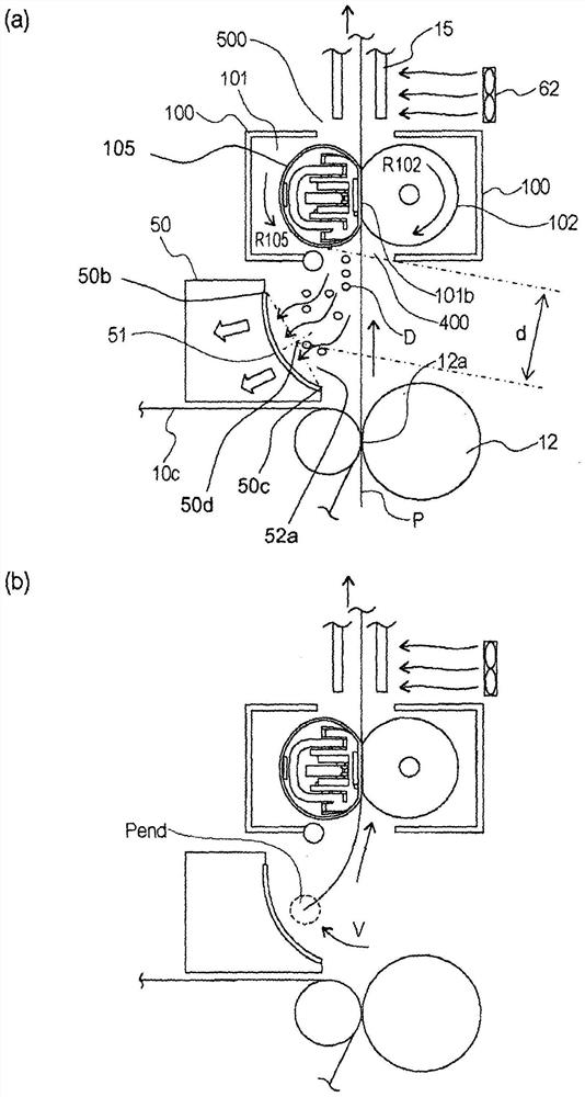
[0254] In Embodiment 1, in order to improve the collection efficiency of the dust D, the air inlet 52a of the duct 52 and the filter 51 are oriented toward the holding portion 101b (toward the belt 105). On the other hand, in Embodiment 2, by orienting the air inlet 52a of the duct 52 toward the transfer portion 12a side, excessive heating of the filter 51 is suppressed. The printer 1 of Embodiment 2 is the same as Embodiment 1 except that the arrangement of the filter unit 50 is different. Th...


PUM


Abstract

Provided is an image forming apparatus capable of properly removing particles generated from a release material contained in toner. The distance d (mm) between the air inlet of the duct and the heating belt is, the area of ​​the non-woven filter Fs (cm 2 ), and the passing wind speed Fv (cm / s) of air in the non-woven fabric filter satisfies the following formula:

Description

technical field [0001] The present invention relates to an image forming apparatus for forming a toner image on a recording material. The image forming apparatus is used as a copier, a printer, a facsimile machine, a multifunction machine having various functions of these machines, and the like. Background technique [0002] An electrophotographic image forming apparatus forms an image on a recording material using a toner containing a release material. In addition, the image forming apparatus includes a fixing device that heats and pressurizes the recording material bearing the toner image and fixes the image on the recording material. [0003] The image forming apparatus described in JP-A-2013-190651 has a structure for collecting ultrafine particles generated by heating a toner containing a release material. [0004] However, with this structure there is room for improvement in properly removing the generated particles. SUMMARY OF THE INVENTION [0005] An object of ...

Claims


Application Information

Patent Timeline
Patent Type & Authority Patents(China)
IPC IPC(8): G03G15/20G03G21/00
CPCG03G15/2017G03G21/206G03G21/0052
Inventor 野岛浩二
Owner CANON KK
Why Eureka
Try Eureka