A lifting hydraulic control system, control method and boarding bridge

A technology of hydraulic control system and lifting cylinder, which is applied to the safety of fluid pressure actuation system, components of fluid pressure actuation system, and mechanical equipment, etc., can solve the problems of rigid function and function of inner drain cylinder, unbalanced load, and hidden safety hazards. , to achieve the effect of stable system motion, high precision, stable and reliable speed control

Active Publication Date: 2020-04-28
SHENZHEN CIMC TIANDA AIRPORT SUPPORT
View PDF1 Cites 0 Cited by
  • Summary
  • Abstract
  • Description
  • Claims
  • Application Information

AI Technical Summary

Problems solved by technology

[0004] 1. The disclosed technical solution cannot monitor and detect the safety status of the oil cylinder in real time, and does not have the function of position detection;
[0005] 2. The rigidity of the lifting cylinder system is insufficient, and it is easy to cause safety hazards due to the leakage of the oil in the cylinder itself;
[0006] 3. The balance valve in this technical solution is directly installed on the oil cylinder, and the pilot control port of the balance valve is directly connected to the other end of the rod chamber of the oil cylinder. It is used as a load control valve for a single oil cylinder, and does not have the ability to prevent internal leakage of the oil cylinder and increase the oil cylinder. Rigidity function and function, for the boarding bridge hydraulic system that generally adopts double cylinders, it is difficult to ensure that the setting pressure of the balance valve of each set of lifting cylinder system is completely consistent, resulting in unbalanced loads on both sides of the descending movement and affecting the boarding bridge The synchronization of the movement of the columns on both sides will affect the stability of the descending movement in severe cases

Method used


Image

  • A lifting hydraulic control system, control method and boarding bridge
  • A lifting hydraulic control system, control method and boarding bridge
  • A lifting hydraulic control system, control method and boarding bridge

Examples


Embodiment Construction

[0029] Example embodiments will now be described more fully with reference to the accompanying drawings. Example embodiments may, however, be embodied in many forms and should not be construed as limited to the embodiments set forth herein; rather, these embodiments are provided so that this disclosure will be thorough and complete, and will fully convey the concept of example embodiments to those skilled in the art. The same reference numerals in the drawings denote the same or similar structures, and thus their detailed descriptions will be omitted.

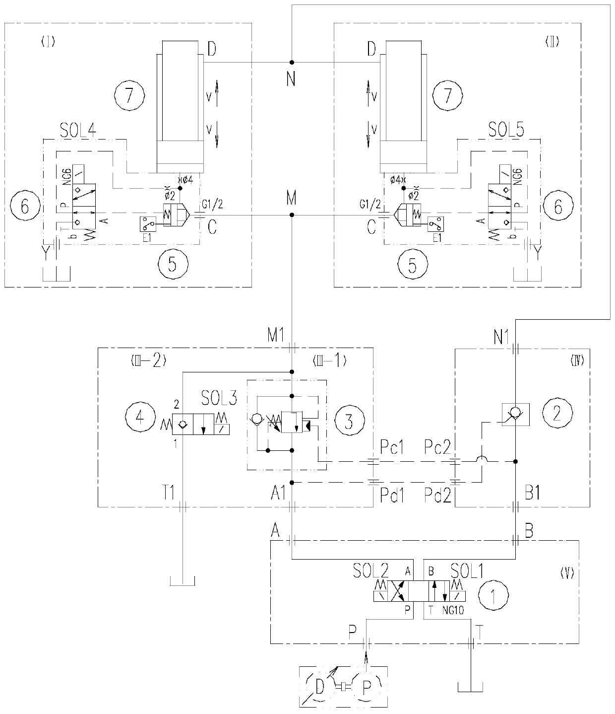
[0030] Such as figure 1 As shown, the present invention provides a lifting hydraulic control system, including: the first lifting cylinder system I with position detection function, load holding function circuit III-1 and reversing function circuit V.

[0031] The first lifting cylinder system with position detection function Ⅰ includes lifting cylinder 7, seat valve with spool detection 5, ball solenoid valve 6 and control o...


PUM


Abstract

Provided are a lifting hydraulic control system and method and a boarding bridge. The lifting hydraulic control system comprises a first lifting oil cylinder system having a first position detecting function, a circuit having a load maintaining function and a circuit having a reversing function. The first lifting oil cylinder system having the first position detecting function comprises a liftingoil cylinder, a detecting seat valve with a valve element, a spherical magnetic valve and a control oil way. The spherical magnetic valve and the detecting seat valve with the valve element jointly form a hydraulic circuit through the control oil way. The circuit having the load maintaining function is communicated with the first lifting oil cylinder system having the first position detecting function, and a balance valve is arranged on the circuit having the load maintaining function. The circuit having the reversing function is communicated with the circuit having the load maintaining function, a three-position four-way directional valve is arranged on the circuit having the reversing function, the circuit having the reversing function is provided with a first reversing oil port, a second reversing oil port and a third reversing oil port, the first reversing oil port is used for connection with an external hydraulic power source, the second reversing oil port is used for connection with an oil tank, and the third reversing oil port is communicated with the circuit having the load maintaining function.

Description

technical field [0001] The invention relates to a hydraulic control system, in particular to a lifting hydraulic control system and a boarding bridge. Background technique [0002] Passenger boarding bridges have developed to this day. With the improvement of domestic and foreign standards for boarding bridge functions and safety requirements, safety standards, especially the protection of aircraft and personnel, have always been placed in the first place in product safety. Controlled actions will directly cause harm to aircraft and personnel. Both EN12312-4-2014 and MH / T6028-2003 require that the boarding bridge control system should be able to detect uncontrolled actions of the boarding bridge and automatically freeze the uncontrolled actions. According to the requirements of the standard, boarding bridge manufacturers must develop corresponding mechanisms and systems to meet the requirements of the industry standard. [0003] The patent application number CN201620035037....

Claims


Application Information

Patent Timeline
Patent Type & Authority Patents(China)
IPC IPC(8): B66F11/00F15B21/08F15B13/02F15B20/00B64F1/305
CPCB64F1/305B66F11/00F15B13/02F15B20/005F15B21/08
Inventor 唐上峰胡少波
Owner SHENZHEN CIMC TIANDA AIRPORT SUPPORT
Why Eureka
Try Eureka