
Hydraulic control system for full-power shifting and reversing tractor gearbox

A hydraulic control system and power shifting technology, applied in transmission control, mechanical equipment, transmission parts, etc., can solve problems such as shortened service life of parts, complex lubrication circuit system, accelerated driver fatigue, etc., to reduce production and manufacturing cost, simplify the layout of the hydraulic system, and avoid the effects of complex systems

Pending Publication Date: 2018-09-25
JILIN UNIV
View PDF0 Cites 3 Cited by
  • Summary
  • Abstract
  • Description
  • Claims
  • Application Information

AI Technical Summary

Problems solved by technology

[0002] At present, agricultural tractors in my country generally use traditional meshing sleeves or synchronizers to shift gears, but this traditional shifting method has the following disadvantages: 1. Agricultural tractors often have a large number of gears, and the driver is cumbersome to operate when shifting gears , resulting in increased driving difficulty and accelerated driver fatigue
2. The wear and tear between the parts in the gearbox is very large, resulting in high temperature in the box and shortening the service life of the parts
3. In the process of shifting, power interruption will inevitably occur, resulting in a large amount of energy loss during the shifting process
However, the lubrication circuit system required for forced lubrication is relatively complicated, which will increase the design difficulty and increase the manufacturing cost

Method used


Image

  • Hydraulic control system for full-power shifting and reversing tractor gearbox
  • Hydraulic control system for full-power shifting and reversing tractor gearbox
  • Hydraulic control system for full-power shifting and reversing tractor gearbox

Examples


Embodiment Construction

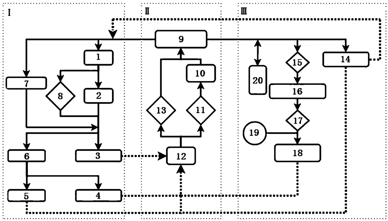
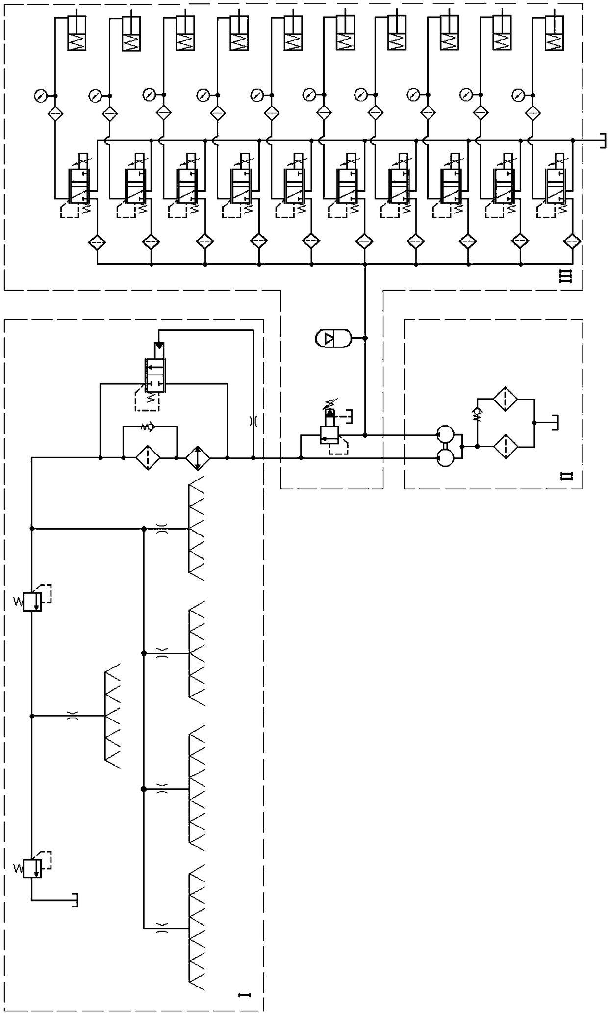
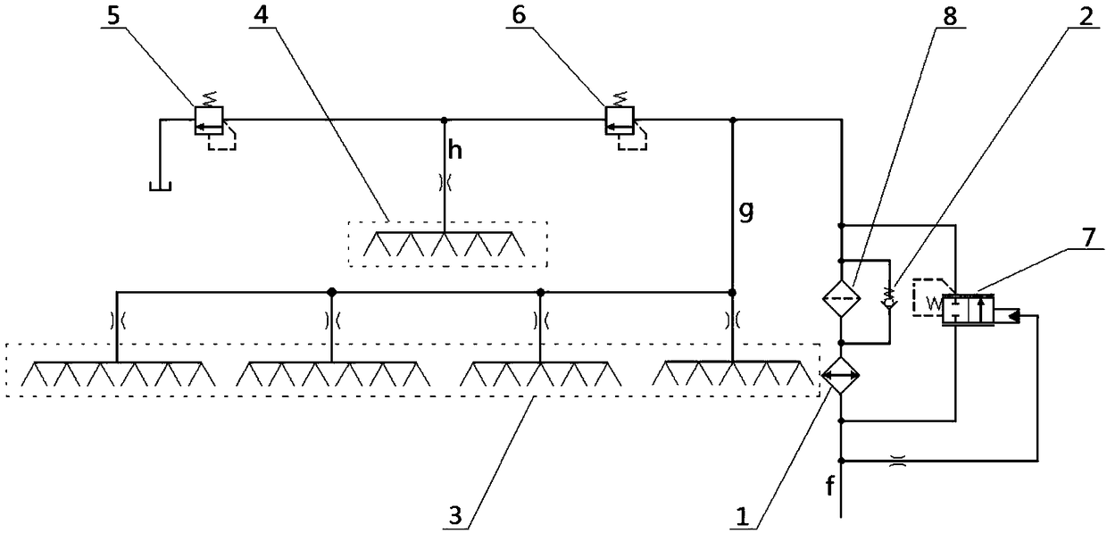
[0041] like figure 1 and figure 2 As shown, the present invention is composed of cooling and lubricating subsystem I, oil supply subsystem II and clutch control subsystem III. The oil inlet of cooler 1 in system Ⅰ is connected; the large displacement oil discharge port i of double gear pump 9 in oil supply subsystem Ⅱ is also connected with the control pilot end of hydraulic control bypass valve 7 in cooling and lubricating subsystem Ⅰ connected. The small displacement oil discharge port j of the dual gear pump 9 in the oil supply subsystem II communicates with the oil inlet port of the pilot overflow valve 14 in the clutch control subsystem III. The overflow oil port of the secondary relief valve 5 in the cooling lubrication subsystem I communicates with the oil return port of the oil tank 12 in the oil supply subsystem II. The overflow oil port of the pilot relief valve 14 in the clutch control subsystem III communicates with the branch circuit where the oil inlet of the...


PUM


Abstract

The invention discloses a hydraulic control system for a full-power shifting and reversing tractor gearbox, and belongs to the technical field of agricultural machinery. The large-displacement oil outlet of a duplex gear pump in an oil supply subsystem is communicated with the oil inlet of a cooler in a cooling and lubricating subsystem and the control guidance end of a hydraulic control bypass-valve in the cooling and lubricating subsystem; the small-displacement oil outlet of the duplex gear pump in an oil supply subsystem is communicated with the oil inlet of a guidance type overflow valvein a clutch control subsystem; the overflow oil hole of a secondary overflow valve in the cooling and lubricating subsystem is communicated with the oil returning hole of an oil tank in the oil supplysubsystem; the overflow oil hole of the guidance type overflow valve in the clutch control subsystem is communicated with a branch where the oil inlet of the cooler in the cooling and lubricating subsystem. According to the hydraulic control system, the duplex gear pump is taken as a power element, and the space of the hydraulic system can be saved. The hydraulic control bypass-valve is arrangedin the cooling and lubricating subsystem, and the problem of system crash due to cooling and filtering branch blockage can be avoided.

Description

technical field [0001] The invention belongs to the technical field of agricultural machinery, and in particular relates to a hydraulic control system for a tractor gearbox with full power shifting and reversing. Background technique [0002] At present, agricultural tractors in my country generally use traditional meshing sleeves or synchronizers to shift gears, but this traditional shifting method has the following disadvantages: 1. Agricultural tractors often have a large number of gears, and the driver is cumbersome to operate when shifting gears , resulting in increased driving difficulty and accelerated driver fatigue. 2. The wear and tear between the parts in the gearbox is very large, resulting in high temperature in the box and shortening the service life of the parts. 3. In the process of shifting gears, it is inevitable that there will be a phenomenon of power interruption, so that a large amount of energy will be lost in the process of shifting gears. [0003] A...

Claims


Application Information

Patent Timeline
Patent Type & Authority Applications(China)
IPC IPC(8): F16H57/04F16H61/40
CPCF16H57/0404F16H57/0413F16H57/0435F16H61/40
Inventor 张志君韩铭雨金柱男孙旭伟陈东辉
Owner JILIN UNIV
Learn More