Environmental vibration testing method and system

A vibration test and environment technology, applied in the field of physical simulation, can solve problems such as difficult to accurately obtain the global vibration response of the test object

Active Publication Date: 2018-09-25
蒙上阳 +1
View PDF4 Cites 3 Cited by
  • Summary
  • Abstract
  • Description
  • Claims
  • Application Information

AI Technical Summary

Problems solved by technology

[0003] The purpose of the present invention is to provide an environmental vibration test method and system to overcome the defect that the existing test equipment is difficult to accurately obtain the global vibration response of the test object

Method used


Image

  • Environmental vibration testing method and system
  • Environmental vibration testing method and system
  • Environmental vibration testing method and system

Examples


Embodiment

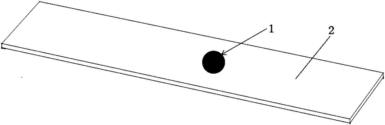
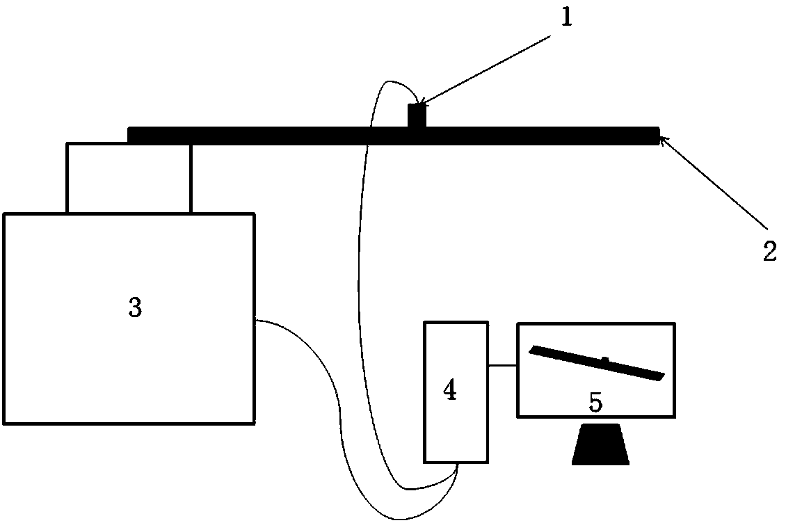
[0196] In this embodiment, for the aluminum beam 2 of rectangular section (such as figure 2 As shown), the environmental vibration test is carried out, and the length, width and height of the aluminum beam 2 are 22cm, 2.8cm and 0.8cm respectively. The vibration experiment table adopts the existing small vibration table. Before the vibration test, a first acceleration sensor (not shown) was arranged on the table of the vibration table, and a second acceleration sensor 1 was arranged at a pre-selected test point on the aluminum beam 2, and then necessary wiring connections were made. image 3 A schematic diagram of an environmental vibration test system according to an exemplary embodiment of the present invention is shown, which includes a vibration table 3 , a first acceleration sensor and a second acceleration sensor 1 , a processor 4 and a display unit 5 .

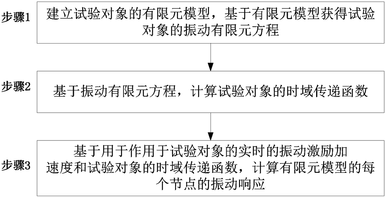
[0197] Follow the steps below to perform the vibration test procedure:

[0198] Step 1: Establish the finite elemen...


PUM


Abstract

Provided are an environmental vibration testing method and system. The method comprises the steps that a finite element model of a tested object is established, and a vibrating finite element equationof the tested object is obtained based on the finite element model; based on the vibrating finite element equation, a time domain transfer function of the tested object is calculated; based on the real-time vibrational excitation acceleration acting the tested object and the time domain transfer function of the tested object, vibration response of each node of the finite element model is calculated. By adopting the environmental vibration testing method and the system, the global vibration response of the tested object can be accurately calculated based on the real-time vibrational excitationacceleration.

Description

technical field [0001] The invention relates to the technical field of physical simulation, in particular to an environmental vibration test method and system. Background technique [0002] Modern aerospace, rail transit, national defense and other equipment all need environmental vibration test evaluation. There are several limitations in the existing physical environment vibration tests: First, the measurement layout space and the number of measuring points are limited, and only the vibration data of a limited number of measuring points can be measured, and the vibration data at any position in the entire area of ​​the test piece cannot be obtained, nor can it be Obtain the situational distribution of the overall vibration of the test piece; second, the environmental vibration test equipment—the physical shaking table has limited thrust, and cannot realize the environmental vibration test of overweight and super large test objects; The physical environment vibration test ...

Claims


Application Information

Patent Timeline
Patent Type & Authority Applications(China)
IPC IPC(8): G06F17/50
CPCG06F30/23
Inventor 蒙上阳段静波牛智勇
Owner 蒙上阳
Why Eureka
Try Eureka