Steel strip clamping device

A clamping device and steel strip technology, which is applied in the field of mechanical processing, can solve the problems of reduced drilling accuracy, inability to clamp the steel strip, and affect operation, etc., and achieve the effects of simple and compact structure, stable device structure, and high work efficiency

Pending Publication Date: 2018-09-28
苏州市翔耀精密自动化设备有限公司
View PDF0 Cites 1 Cited by
  • Summary
  • Abstract
  • Description
  • Claims
  • Application Information

AI Technical Summary

Problems solved by technology

At present, some clamping devices on the market cannot clamp the steel strip tightly. If the steel strip is not fixed and clamped, the steel strip will move and the precision of drilling will be greatly reduc

Method used


Image

  • Steel strip clamping device
  • Steel strip clamping device
  • Steel strip clamping device

Examples


Embodiment

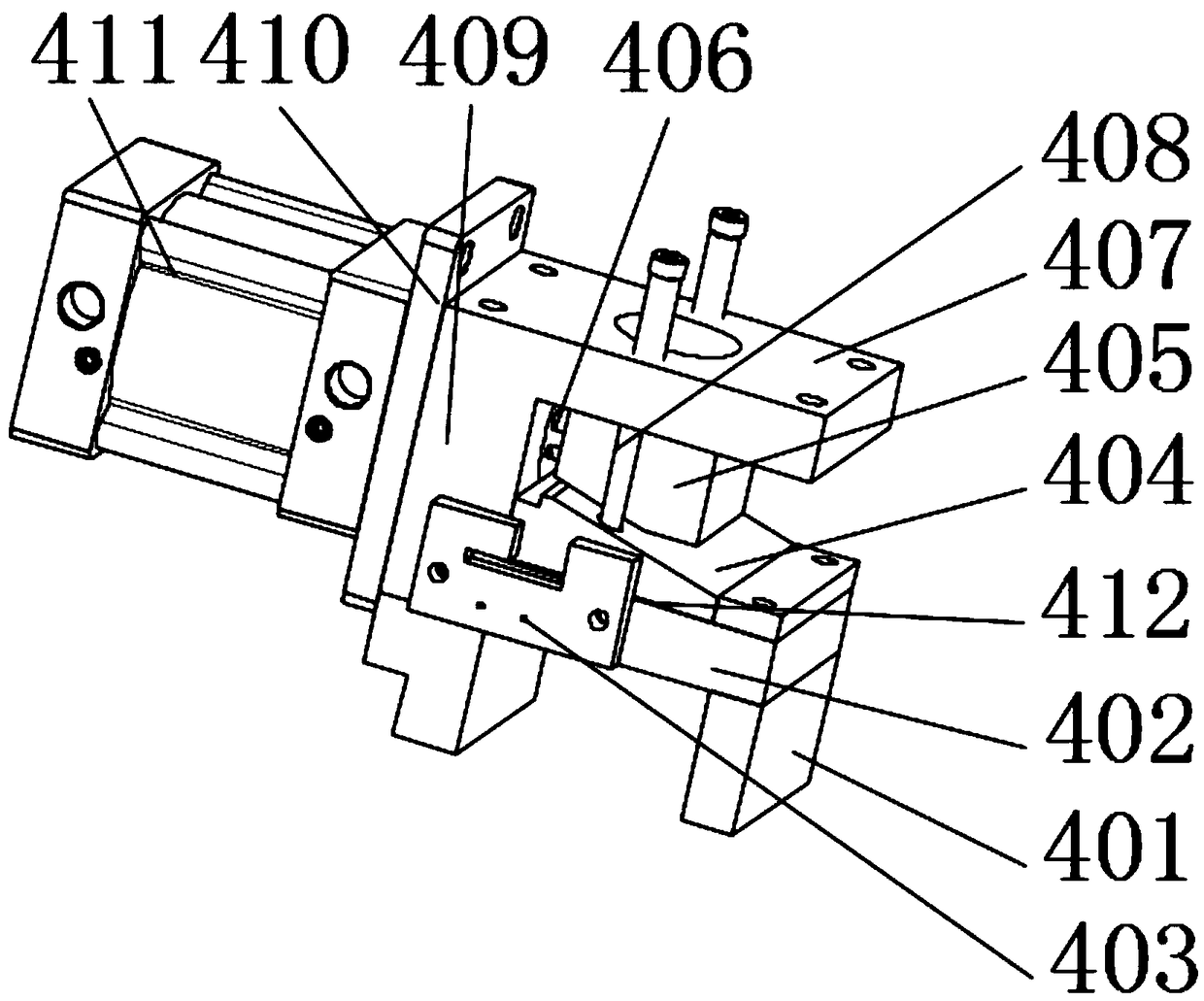
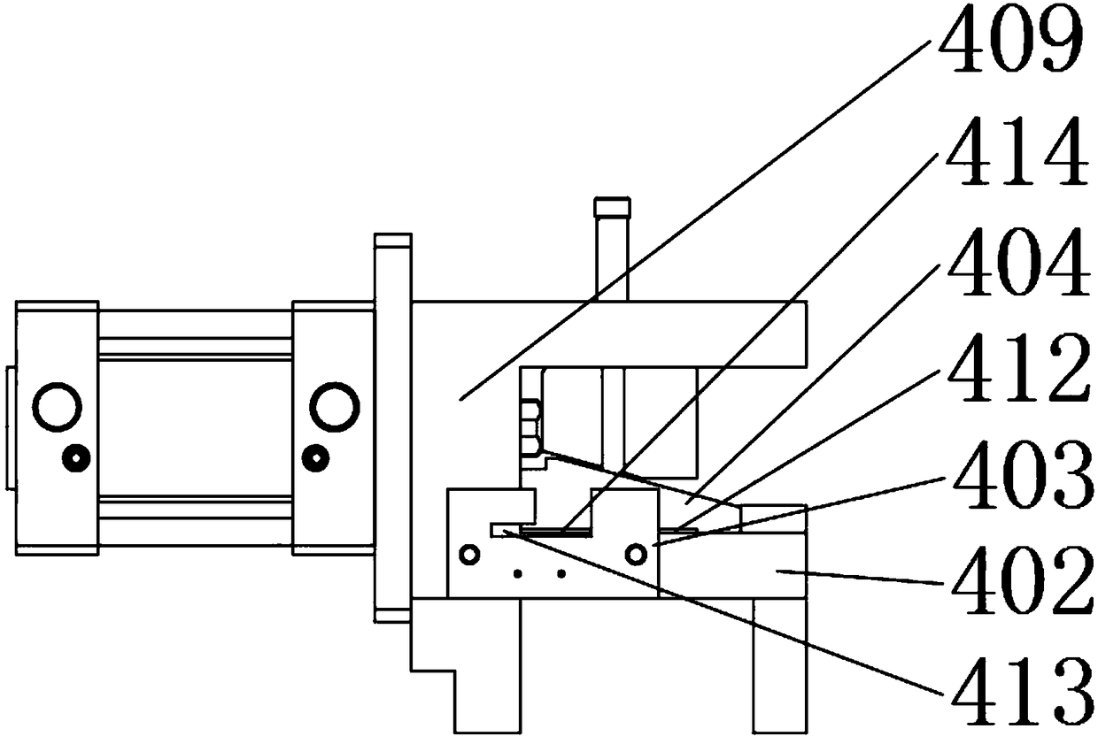
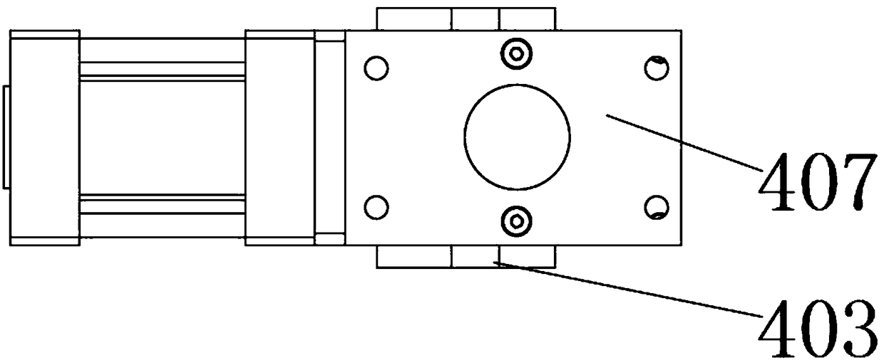
[0026] refer to Figure 1 to Figure 4 As shown, the present invention discloses a steel strip clamping device, which includes a fixed block 401, a base set on the fixed block 401, and a right-angled U-shaped structure formed integrally with the base, including a lower base 402, a side base 409 and an upper base 407. Two guiding columns 408 are fixedly connected to the upper surface of the lower base 402 , and the guiding columns 408 are arranged perpendicular to the lower base 402 . Between the upper base 407 and the lower base 402, a clamping block 404 with an inclined surface is arranged, and the lower surface of the clamping block 404 is provided with an upwardly concave rectangular groove 412 in the direction of steel strip transmission, and the rectangular groove 412 is used to place the steel strip . Two holes are provided inside the clamping block 404 , and the guide post 408 is sheathed in the hole of the clamping block 404 , and the clamping block 404 can move back ...


PUM


Abstract

The invention discloses a steel strip clamping device. The steel strip clamping device comprises a lower base, a clamping block and a power block; the lower base is horizontally arranged; the clampingblock can move up and down to extrude the lower base; the power block can move left and right to provide power to the clamping block; a rectangular groove, upwards projected, is formed in the lower surface of the clamping block in a steel strip conveying direction; the upper surface of the clamping block and the lower surface of the power block are both inclined surface and tightly bonded; a guide column is vertically arranged on the lower base, and penetrates through the clamping block; and the power block is connected with a motion output end of a driving source. The steel strip clamping device can tightly clamp steel strips without damaging the steel strips, and is simple and compact in structure and small in size.

Description

technical field [0001] The invention relates to the technical field of machining, in particular to a steel strip clamping device. Background technique [0002] In industrial production, the steel strip needs to be tightly clamped and fixed during mechanical operations such as punching the steel strip. At present, some clamping devices on the market cannot tightly clamp the steel strip. If the steel strip is not fixed and clamped, the steel strip will move, and the precision of punching will be greatly reduced. There are also some clamping devices that can tightly clamp the steel strip, but during the clamping process, the steel strip is deformed due to excessive clamping force, which affects subsequent operations. Contents of the invention [0003] The technical problem to be solved by the present invention is to provide a steel strip clamping device, which can tightly clamp the steel strip without causing damage to the steel strip, and has a simple and compact structure ...

Claims


Application Information

Patent Timeline
IPC IPC(8): B23B47/00B23Q3/08
CPCB23B47/00B23Q3/08B23Q3/082
Inventor 许晓华
Owner 苏州市翔耀精密自动化设备有限公司
Why Eureka
Try Eureka