Supercharge Your Innovation With Domain-Expert AI Agents!

Spatial movement path planning method for laser cutting

A path planning and laser cutting technology, applied in laser welding equipment, welding equipment, metal processing equipment, etc., can solve problems such as collision, cutting head scrap, plate deformation, etc., to achieve the effect of convenient use and collision avoidance

Inactive Publication Date: 2018-09-28
上海柏楚电子科技股份有限公司
View PDF5 Cites 7 Cited by
  • Summary
  • Abstract
  • Description
  • Claims
  • Application Information

AI Technical Summary

Problems solved by technology

After the laser machine completes the cutting of the current part, the cutting head is lifted up and moved to the next point at high speed. If the process passes through the cut part, a collision may occur, resulting in the scrapping of the cutting head or deformation of the plate

Method used


Image

  • Spatial movement path planning method for laser cutting
  • Spatial movement path planning method for laser cutting

Examples


Embodiment

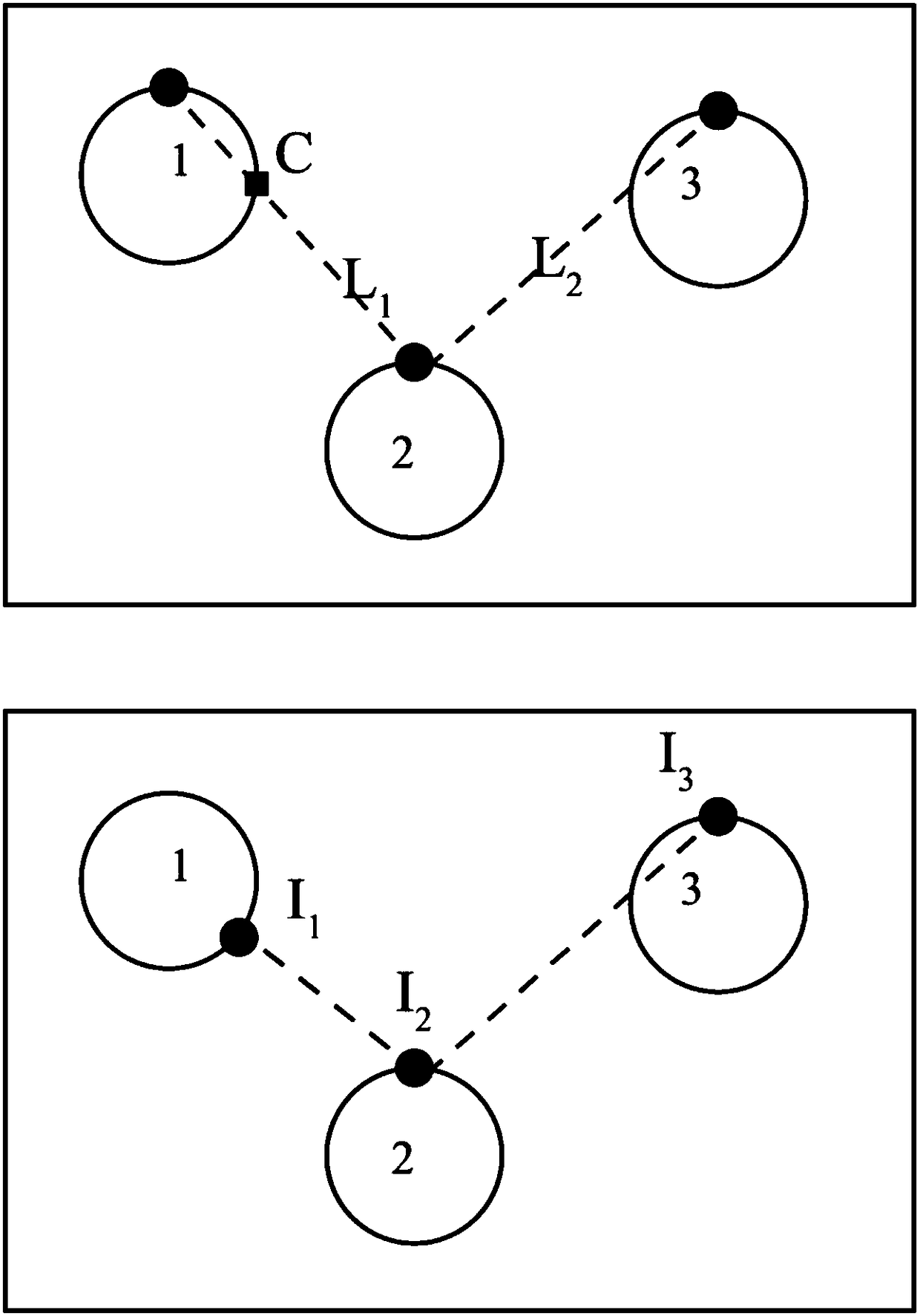
[0014] Such as figure 2 as shown, figure 2 The upper middle picture shows the original moving path of the laser head. The dots on part 1, part 2 and part 3 are the starting points of part cutting. The line between part 1 and part 2 is L1, and the line between part 2 and part 3 is The connection between is L2; figure 2 The middle and lower picture shows the planned air movement path of the laser head, and the dots on parts 1, 2, and 3 are the starting points I1, I2, and I3 of the laser head air movement. Find the cutting starting position of part 1 and part 2, and connect the two starting positions to form L1, and the remaining part 1 of L1 intersects at point C; the connection line L3 of part 2 and part 3 is the same. The head moves directly from the starting point of part 1 to the starting point of part 2 along L1, and then moves along L2 to the starting point of part 3. In the process of moving from part 1 to part 2, the laser head is very likely to Collision with the ...


PUM


Abstract

The invention relates to the field of laser cutting, and specifically relates to a spatial movement path planning method for laser cutting. The spatial movement path planning method for laser cuttingcomprises the following steps: S1, starting treatment software of a laser cutting machine, leading in parts to be cut, carrying out stock layout, and determining the machining sequence for the parts;S2, searching the nth part and the (n+1)th part, determining the initial cutting positions of the two parts, calculating whether the connection line between the two initial positions has an intersection point C with the nth part or not, if so, executing step S3, or else, denoting the origin of the nth part as In and executing step S4; S3, searching the origin In enabling Ln to be not intersected with the outer contour of the nth part on the outer contour of the nth part; S4, repeating the steps S2 and S3, and searching the origin In+1 of the (n+1)th part; and S5, sequentially connecting In toIn+1 to generate a spatial movement path. Compared with the prior art, the spatial movement path planning method for laser cutting is convenient to use, capable of guaranteeing that a cutting head cannot pass through the currently-cut part in a spatial movement process, and capable of furthest avoiding the collision caused due to the upward lifting and spatial movement of the cutting head.

Description

technical field [0001] The invention relates to the field of laser cutting, in particular to a space-moving path planning method for laser cutting. Background technique [0002] In the process of laser cutting, the planning of the moving path has always been a basic problem. The planning of the air movement path is a solution to the possible collision with the cut parts during the air movement of the planar laser cutting. After the laser machine finishes cutting the current part, it lifts the cutting head and moves to the next point at high speed. If the process passes through the cut parts, collision may occur, causing the cutting head to be scrapped or the plate to be deformed. When the software generates the air movement path, it needs to be optimized for this situation to ensure that the air movement path does not pass above the current cutting part, so as to reduce the distance and times of lifting the cutting head, improve processing efficiency and ensure safety. Co...

Claims


Application Information

Patent Timeline
IPC IPC(8): B23K26/38B23K26/08
CPCB23K26/38B23K26/08
Inventor 代田田江舟亚
Owner 上海柏楚电子科技股份有限公司
Features
  • R&D
  • Intellectual Property
  • Life Sciences
  • Materials
  • Tech Scout
  • Unparalleled Data Quality
  • Higher Quality Content
  • 60% Fewer Hallucinations
Learn More