Compound and organic luminescence display device

A compound and organic technology, applied in the field of organic electroluminescent materials, can solve the problems of poor stability of phosphorescent devices, roll-off of phosphorescent material efficiency, unfavorable mass production, etc., to reduce the problem of exciton quenching and satisfy device performance , strong effect

Active Publication Date: 2018-09-28
WUHAN TIANMA MICRO ELECTRONICS CO LTD
View PDF11 Cites 20 Cited by
  • Summary
  • Abstract
  • Description
  • Claims
  • Application Information

AI Technical Summary

Problems solved by technology

However, phosphorescent materials are basically heavy metal complexes such as Ir, Pt, Os, Re, Ru, etc., and the production cost is high, which is not conducive to large-scale production; and at high current densities, phosphorescent materials have a serious efficiency roll-off phenomenon; in addition, The stability of phosphorescent devices is also not good

Method used


Image

  • Compound and organic luminescence display device
  • Compound and organic luminescence display device
  • Compound and organic luminescence display device

Examples


preparation example Construction

[0121] The preparation method of the compound according to the present invention may include the following steps: respectively reacting the activated thienyl group with the D unit and the A unit to obtain the compound.

[0122] The preparation methods and results of several specific compounds are given below.

[0123]

[0124] Intermediates S1, S4, S8, S12, S13, S14, S17, S23, S25, S28, and S29 are all commercially available products.

[0125] Synthesis of Compound P1

[0126] Synthesis of intermediate S3

[0127]

[0128] S1 (10mmol), 9,9-dimethyl-9,10-dihydroacridine S2 (10.5mmol), (dibenzylideneacetone) dipalladium (0) (0.05mmol), sodium tert-butoxide ( 14mmol), 4,5-bisdiphenylphosphine-9,9-dimethylxanthene (0.2mmol) were put into a 50mL three-necked flask, and while stirring, the degassing and nitrogen replacement were repeated three times rapidly, and the 20mL of toluene. The mixture was heated to reflux for 3 hours under nitrogen flow. After the reaction, wate...

Embodiment 1~8

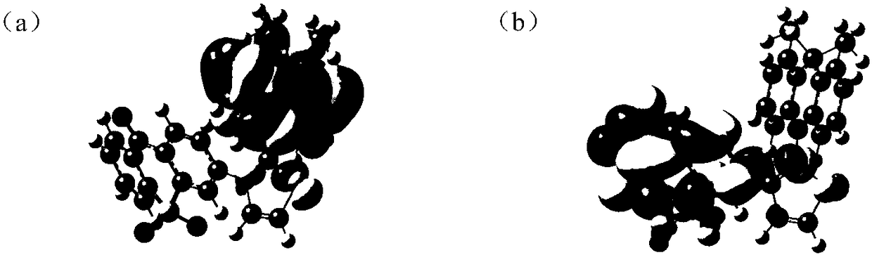
[0259] figure 1 Shows the orbital arrangement of compound P1, where, figure 1 (a) is the HOMO energy level distribution diagram of compound P1, figure 1 (b) is the LUMO energy level distribution diagram of compound P1. from figure 1 It can be clearly seen that the HOMO and LUMO of compound P1 are arranged on different units, achieving complete separation, which helps to reduce the intersystem energy difference △E ST , so as to improve the reverse intersystem crossing ability.

[0260] Using density functional theory (DFT), for compounds P1~P6, P21, P30, using the Gaussian 09 program package at the B3LYP / 6-31G(d) calculation level, the distribution of molecular frontier orbitals was optimized and calculated; at the same time Based on the time-dependent density functional theory (TDDFT), the singlet energy level S of the molecule is simulated and calculated 1 and the triplet energy level T 1 .

[0261] The relevant data of Examples 1-8 are shown in Table 1. It can be see...


PUM


Abstract

The invention relates to the technical field of organic electroluminescent materials, in particular to a compound and an organic luminescence display device. The compound has a structure shown by formula (I) in the description, wherein D represents an electron donor unit; A represents an electron receiver unit; m and n are respectively and independently selected from 1, 2 or 3; in addition, the sum of the m and the n is smaller than or equal to 4. When the compound is used as a luminous material, an object material or a main body material of the organic luminescence display device, high luminescence efficiency can be realized.

Description

technical field [0001] The invention relates to the technical field of organic electroluminescence materials, in particular to a compound and an organic light-emitting display device. Background technique [0002] According to the light-emitting mechanism, there are mainly four kinds of materials that can be used for the light-emitting layer of OLEDs: fluorescent materials, phosphorescent materials, triplet-triplet annihilation (TTA) materials, and thermally activated delayed fluorescence (TADF) materials. Among them, the theoretical maximum internal quantum yield of fluorescent materials does not exceed 25%, the theoretical maximum internal quantum yield of TTA materials does not exceed 62.5%; the theoretical maximum internal quantum yield of phosphorescent materials and TADF materials can reach 100%. However, phosphorescent materials are basically heavy metal complexes such as Ir, Pt, Os, Re, Ru, etc., and the production cost is high, which is not conducive to large-scale ...

Claims


Application Information

Patent Timeline
Patent Type & Authority Applications(China)
IPC IPC(8): C07D409/14C07F5/02C07D409/04C07D333/36C07D413/14C07D519/00C07F9/6571C07D471/06C07D409/10C07D491/048C07F7/10C09K11/06H01L51/50H01L51/54
CPCC07D333/36C07D409/04C07D409/10C07D409/14C07D413/14C07D471/06C07D491/048C07D519/00C07F5/02C07F7/0816C07F9/657163C09K11/06C09K2211/1088C09K2211/1092C09K2211/1096C09K2211/1029C09K2211/1007C09K2211/1014C09K2211/1059C09K2211/1033C09K2211/1037C09K2211/104H10K85/655H10K85/654H10K85/657H10K85/6576H10K85/6572H10K50/11H10K85/636H10K85/322H10K2101/40H10K2101/10H10K2101/30H10K2101/20H10K50/12
Inventor 高威王湘成张磊牛晶华
Owner WUHAN TIANMA MICRO ELECTRONICS CO LTD
Why Eureka
Try Eureka