Automatic quenching device of hardware metal parts

A technology of metal parts and quenching devices, which is applied in the field of mechanical processing, can solve problems such as low automation and high labor intensity, and achieve the effects of improving production efficiency, convenient operation, and simple overall structure

Inactive Publication Date: 2018-09-28
李冰雪
View PDF4 Cites 4 Cited by
  • Summary
  • Abstract
  • Description
  • Claims
  • Application Information

AI Technical Summary

Problems solved by technology

[0002] Quenching is one of the basic means to strengthen steel. Quenching steel into martensite and then tempering to improve toughness is a traditional method to obtain high comprehensive mechanical properties of steel. Heating the metal workpiece to a certain temperature and maintaining it for a period of time Time, then immersed in the quenching medium to quickly cool the metal heat treatment process, the working ability of the hardware tool generally depends on the strength and rigidity, the hardware tool is quenched, so that the rigidity and strength of the hardware tool are improved, so that it is more durable and of higher quality ; However, when quenching hardware tools, it is carried out manually, so there is a problem of high labor intensity, and the degree of automation is low

Method used


Image

  • Automatic quenching device of hardware metal parts
  • Automatic quenching device of hardware metal parts

Examples


Embodiment Construction

[0016] The following will clearly and completely describe the technical solutions in the embodiments of the present invention with reference to the accompanying drawings in the embodiments of the present invention. Obviously, the described embodiments are only some, not all, embodiments of the present invention. Based on the embodiments of the present invention, all other embodiments obtained by persons of ordinary skill in the art without making creative efforts belong to the protection scope of the present invention.

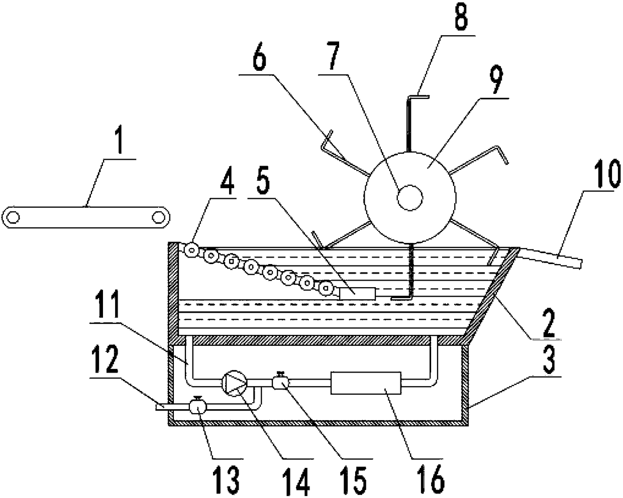
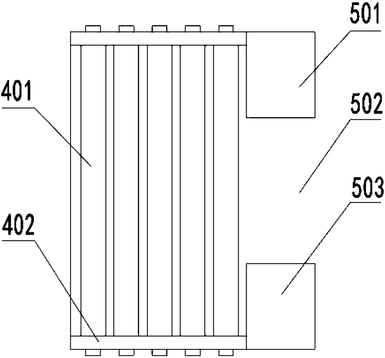
[0017] see Figure 1~2 , in an embodiment of the present invention, an automatic quenching device for hardware and metal parts, including a feeding conveyor belt 1, a quenching pool 2, a base 3, a transfer mechanism 5, a loading plate 6 and a blanking plate 10, the quenching pool 2 A feeding conveyor belt 1 for feeding is installed at one side of the quenching pool 2, and a sliding roller table 4 is installed obliquely in the quenching pool 2. The highest poin...


PUM


Abstract

The invention discloses an automatic quenching device of hardware metal parts. The automatic quenching device comprises a feeding conveyor belt, a quenching tank, a base, a switching mechanism, material carrying plates and a discharging plate, wherein a feeding conveying belt used for feeding is arranged at one side of the quenching tank, a sliding roller way which is obliquely arranged is arranged in the quenching tank, the position of the highest point of the sliding roller way corresponds to the end of the feeding conveying belt, the switching mechanism is connected to the position of the bottom end of the sliding roller way, the sliding roller way and the switching mechanism are arranged below liquid level in the quenching tank, a rotating shaft is further installed at the position above the quenching tank, a rotating cylinder is fixed outside the rotating shaft, and the plurality of material carrying plates are uniformly fixed on the outer circumference of the rotating cylinder. The automatic quenching device has the beneficial effects that the sliding roller way, the switching mechanism and the material carrying plates are arranged, so that automatic falling, transferring, quenching and discharging actions of metal parts can be realized, the manual participation is basically not needed, the production efficiency is greatly improved, the overall structure is relatively simple, and the operation is convenient.

Description

technical field [0001] The invention relates to the technical field of mechanical processing, in particular to an automatic quenching device for hardware and metal parts. Background technique [0002] Quenching is one of the basic means to strengthen steel. Quenching steel into martensite and then tempering to improve toughness is a traditional method to obtain high comprehensive mechanical properties of steel. Heating the metal workpiece to a certain temperature and maintaining it for a period of time Time, then immersed in the quenching medium to quickly cool the metal heat treatment process, the working ability of the hardware tool generally depends on the strength and rigidity, the hardware tool is quenched, so that the rigidity and strength of the hardware tool are improved, so that it is more durable and of higher quality ; But it is manually carried out when quenching the hardware tools, so there is a problem of high labor intensity, and the degree of automation is lo...

Claims


Application Information

Patent Timeline
Patent Type & Authority Applications(China)
IPC IPC(8): C21D1/64
CPCC21D1/64
Inventor 李冰雪
Owner 李冰雪
Why Eureka
Try Eureka