
Ceiling joist and sliding rail integrated system

An integrated system and keel technology, applied in the direction of the ceiling, building components, hanging curtain devices, etc., can solve the problem that the corner of the slide rail and the connection between the corner and the main and auxiliary keels of the ceiling, the unreasonable setting of the ceiling keel structure and accessories, and the product The use of pulleys is not smooth and other problems, to achieve the effect of convenient maintenance or replacement of pulleys, high safety, and aesthetics

Pending Publication Date: 2018-09-28
深圳市华宇新材科技有限公司
View PDF0 Cites 0 Cited by
  • Summary
  • Abstract
  • Description
  • Claims
  • Application Information

AI Technical Summary

Problems solved by technology

[0003] 1. The keel and the slide rail are two sets of systems respectively, two sets of installation and load-bearing structures, the installation is complicated, the safety is poor, the cost is high, and the visual effect is poor;
[0004] 2. At present, the ceiling joist integrated slide rail system on the market cannot solve the problem of the required corner of the slide rail and the connection between the corner and the main and auxiliary ceiling joists. The use of pulleys is not smooth; in addition, the ceiling keel designed by each ceiling manufacturer can only be equipped with its own special keel and plate, and cannot be fully marketed

Method used


Image

  • Ceiling joist and sliding rail integrated system
  • Ceiling joist and sliding rail integrated system
  • Ceiling joist and sliding rail integrated system

Examples


Embodiment Construction

[0037] The present invention will be further described below in conjunction with the accompanying drawings and specific embodiments. Terms such as "upper", "lower", "left", "right", "middle" and "one" quoted in the preferred embodiment are only for convenience of description, and are not used to limit the scope of the present invention. The scope of implementation and the change or adjustment of its relative relationship shall also be regarded as the scope of implementation of the present invention without substantive changes in technical content.

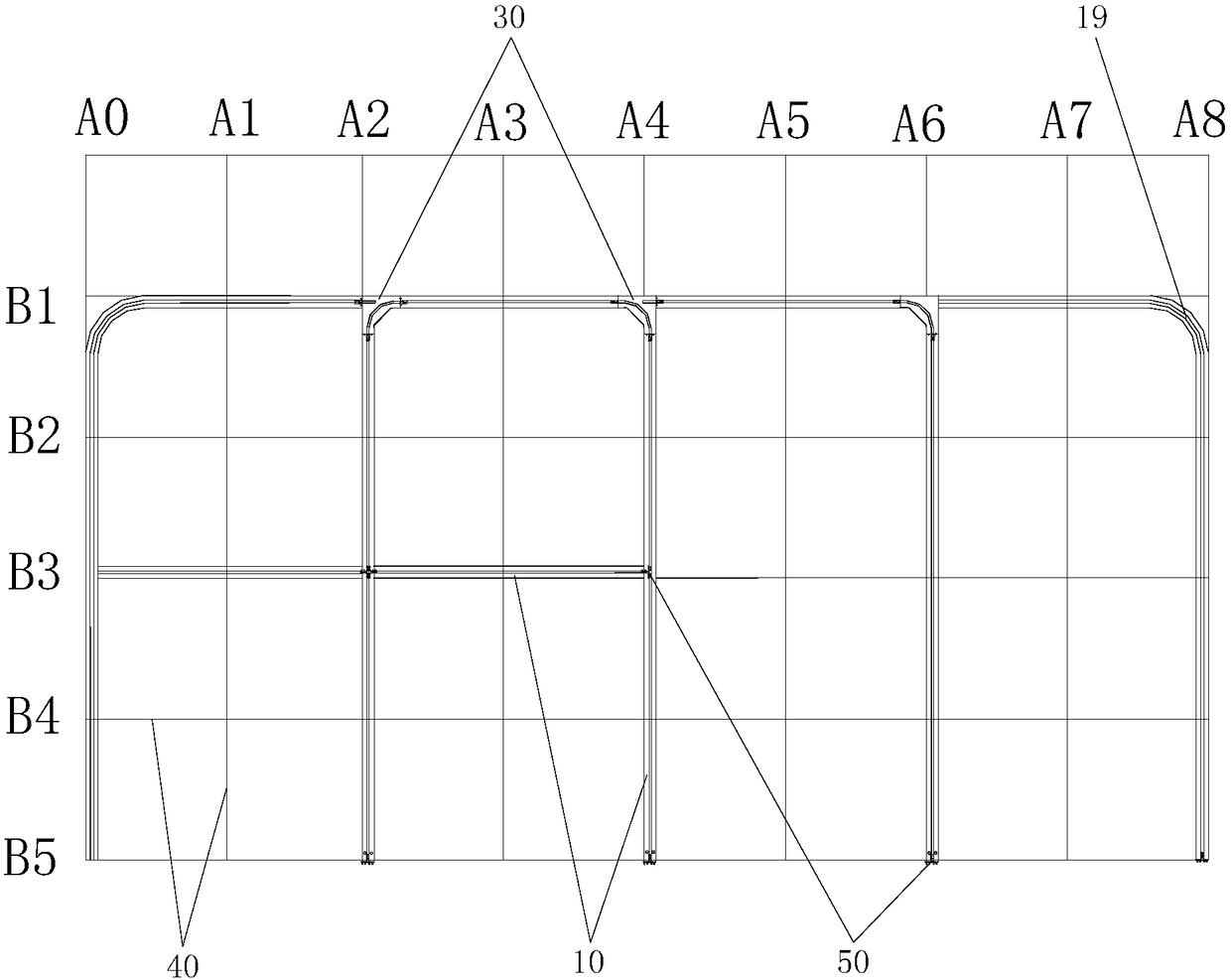
[0038] See figure 1 , a ceiling joist and slide rail integrated system designed in a preferred embodiment of the present invention, which mainly includes: a slide rail formed by a plurality of strip ceiling joists 10 staggered horizontally and vertically, and a pulley mounted on the slide rail. The following details Describe the components and their connections.

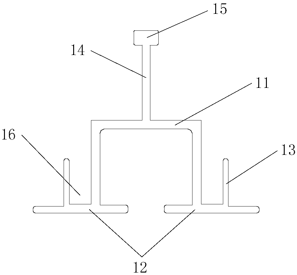
[0039] See figure 2 , The ceiling keel 10 includes: a wheel fram...


PUM


Abstract

A ceiling joist and sliding rail integrated system comprises a sliding rail formed by a plurality of ceiling joists which are spliced in a transversely and vertically staggered mode, a joist corner piece and a pulley. Each ceiling joist comprises a wheel stand groove, and supporting plates are arranged at the two parallel bottom edges of each wheel stand groove correspondingly. A web is arranged in the center of the top of each wheel stand groove, and a flange is arranged at the top of each web. The bottom end face of the joist corner piece is a ceiling supporting plate face, a circular-arc groove of 90 degrees is formed in the ceiling supporting plate face, and the two ends of each circular-arc groove extend to be provided with linear grooves. Each linear groove is in butt joint with oneend of each wheel stand groove, and a first bayonet is convexly formed in the position, corresponding to the end of corresponding circular-arc groove, of the upper end of the joist corner piece. Screwholes are formed in the side wall of the first bayonet in a penetrating mode, and one end of each web is inserted into the first bayonet. The upper end and the lower end of the first bayonet are connected with the bottom end faces of the flanges and the top end faces of the wheel stand grooves in an abutting mode, and screws are used for being inserted into the screw holes to connect and fix thewebs. The assembly structure is simpler, the production difficulty is lowered, the ceiling joists and the joist corner piece are connected for integration, and the rotating direction of the sliding rail is changed flexibly according to the actual demands.

Description

technical field [0001] The invention relates to a special-purpose ceiling keel and slide rail integration system. The system integrates the ceiling keel, slide rails, inspection openings, keel corner pieces and connecting pieces. It is used in the ceiling specification boards that need to use exposed keels, which can include: slide rails that need to be turned for office curtains, integrated curtain boxes and curtain slide rails; ward curtains, infusion keels, and office places that need to use curtains or curtains . Background technique [0002] There are two technical solutions currently on the market: [0003] 1. The keel and the slide rail are two sets of systems respectively, two sets of installation and load-bearing structures, the installation is complicated, the safety is poor, the cost is high, and the visual effect is poor; [0004] 2. At present, the ceiling joist integrated slide rail system on the market cannot solve the problem of the required corner of the s...

Claims


Application Information

Patent Timeline
IPC IPC(8): E04B9/06A47H1/04A47H15/04E04B9/12
CPCA47H1/04A47H15/04E04B9/06E04B9/12A47H2001/045
Inventor 彭文广袁崇伟赖清秀戴凯生
Owner 深圳市华宇新材科技有限公司
Learn More