Wire frame sphere joint positioning rapid adjustment device and installation adjustment method thereof

A node positioning and adjusting device technology, which is applied in the direction of construction, building structure, and building materials processing, can solve the problems of ball joint elevation difficult to place at one time, low construction efficiency, and difficulty in taking out pads, etc., to achieve improved assembly Construction efficiency, high installation accuracy, and high construction efficiency

Pending Publication Date: 2018-09-28
THE SECOND CONSTR ENG CO LTD OF CHINA CONSTR THIRD ENG BUREAU
View PDF0 Cites 6 Cited by
  • Summary
  • Abstract
  • Description
  • Claims
  • Application Information

AI Technical Summary

Problems solved by technology

During the positioning and installation of ball joints, the height of each ball joint is inconsistent, and the height of each ball joint needs to be adjusted continuously during the construction process, resulting in low construction efficiency
The traditional construction method is to pad the lower part of the ball joint to the design elevation. This process is often time-consuming and laborious. The elevation of the ball joint is difficult to put in place at one time, and the precision control is poor.
After the grid frame is assembled, it is necessary to remove the pads under the ball nodes, but at this time the ball nodes are still in a state of stress, and the ball nodes and the pads are still in close contact. It is difficult to remove the pads and unload them.

Method used


Image

  • Wire frame sphere joint positioning rapid adjustment device and installation adjustment method thereof
  • Wire frame sphere joint positioning rapid adjustment device and installation adjustment method thereof
  • Wire frame sphere joint positioning rapid adjustment device and installation adjustment method thereof

Examples


Embodiment Construction

[0016] The following will clearly and completely describe the technical solutions in the embodiments of the present invention with reference to the accompanying drawings in the embodiments of the present invention. Obviously, the described embodiments are only some, not all, embodiments of the present invention.

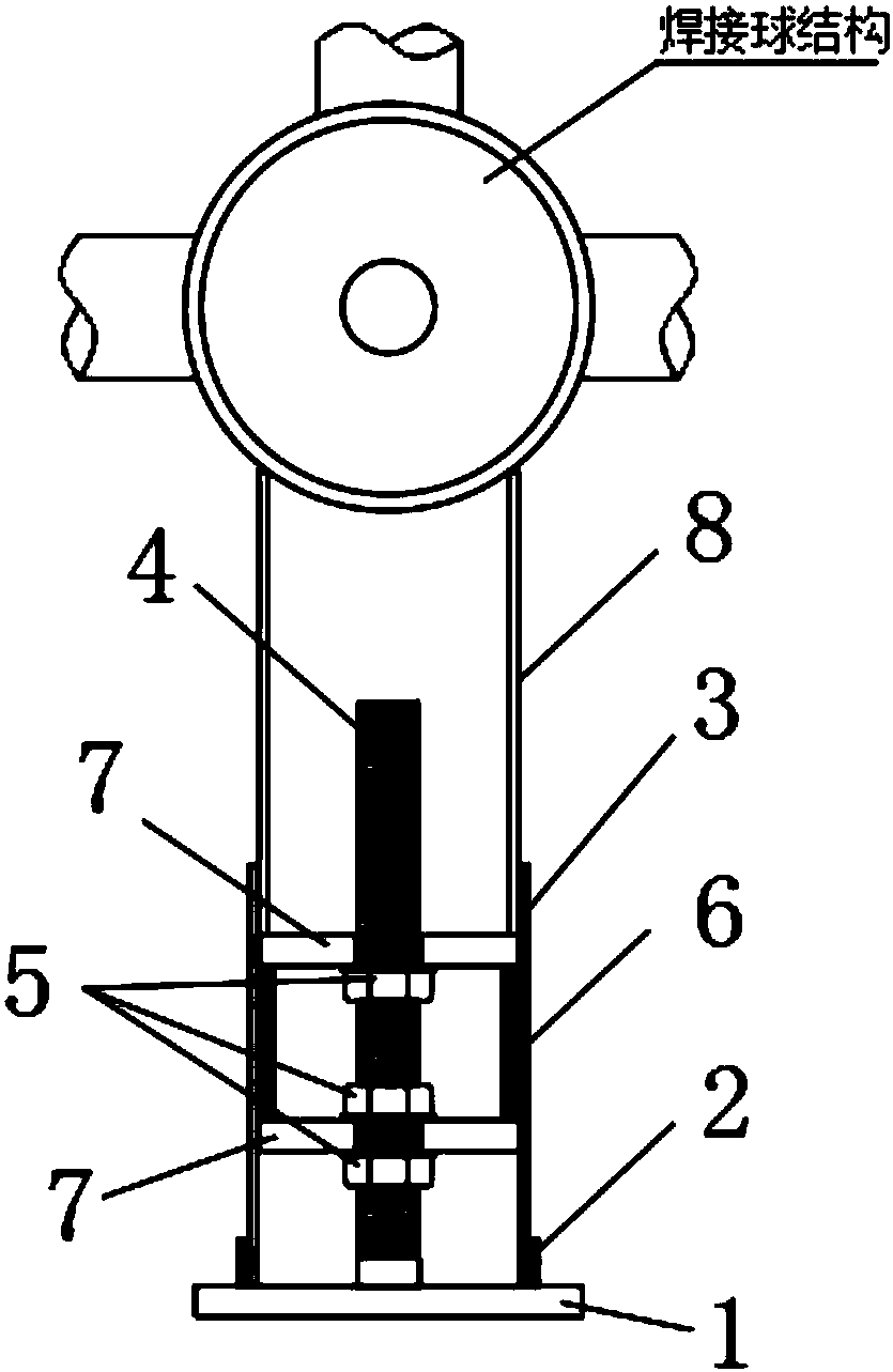
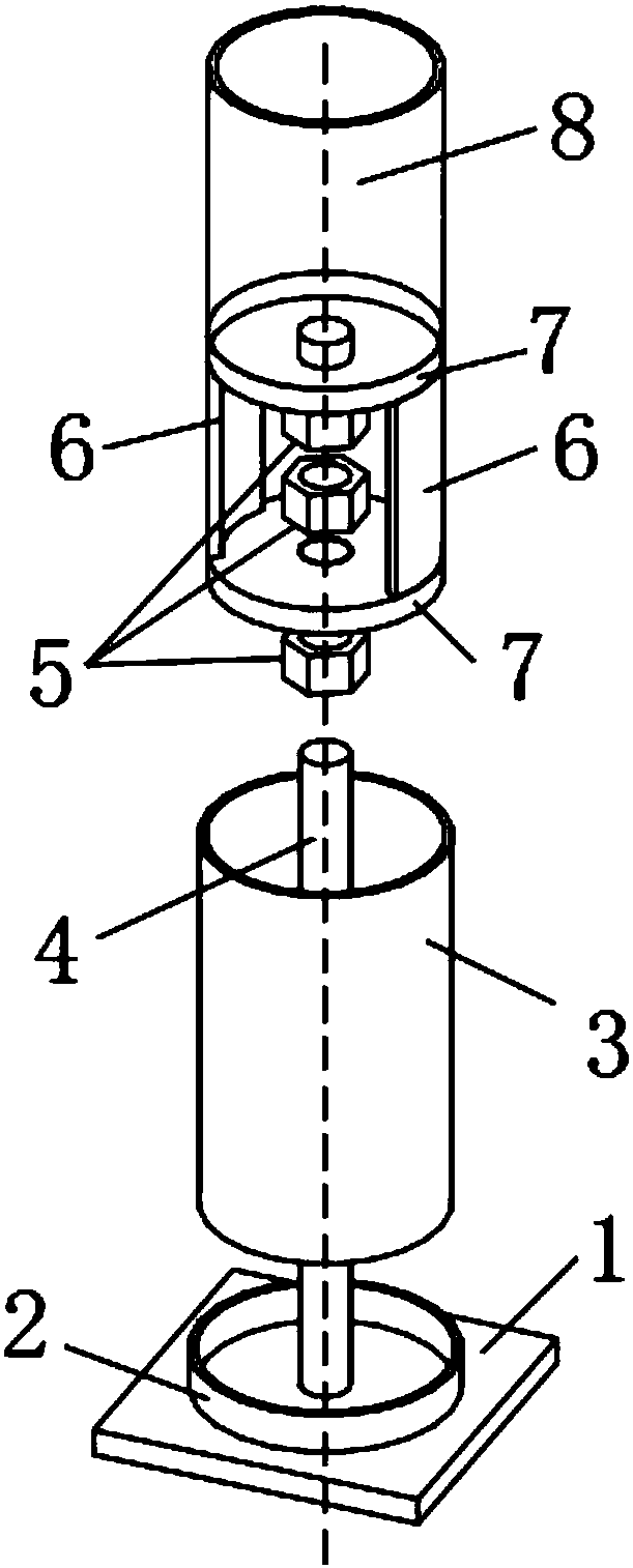
[0017] Such as Figure 1 to Figure 4 As shown in the figure, a fast adjustment device for positioning ball joints of a network frame includes a base plate 1, a fixed hoop steel pipe 2, a threaded round rod 4, an arc plate 6 and a supporting steel pipe 8; the upper surface of the base plate 1 is provided with a ring Shaped fixed hoop steel pipe 2, the base plate 1 is fixed with a threaded round rod 4 in the direction of the vertical axis of the fixed hoop steel pipe 2; two arc-shaped plates 6 are arranged on the outside of the threaded round rod 4, and , the lower two ends are respectively provided with a force transmission plate 7; the force transmission plate 7 at t...


PUM


Abstract

The invention discloses a wire frame sphere joint positioning rapid adjustment device. The wire frame sphere joint positioning rapid adjustment device comprises a base plate, a threaded round rod anda supporting steel pipe. A circular fixing hoop steel pipe is arranged on the surface of the base plate, and the threaded round rod is fixed to position, in the vertical axis direction of the fixing hoop steel pipe, of the base plate. Two curved plates are arranged on the outer side of the threaded round rod, and force transmitting plates are separately arranged on the upper and lower ends of thecurved plates. The supporting steel pipe is fixed to the force transmitting plate at the upper end. A movable hoop steel pipe is arranged between the supporting steel pipe and the fixing hoop steel pipe. Three hexagonal lock nuts are arranged on the threaded round rod, two of the hexagonal lock nuts are located between the two force transmission plates, another hexagonal lock nut is located belowthe force transmission plate at the lower part, and the hexagonal lock nuts are used for height adjustment and locking. The structural design of the wire frame sphere joint positioning rapid adjustment device is reasonable, and the upper and lower adjustment and rapid positioning and unloading can be realized, the assembly construction efficiency of a sphere joint wire frame is improved, the eccentric compression of the threaded round rod is reduced, the relative offset is not generated, and the fixation reliability is high.

Description

technical field [0001] The invention relates to the technical field of welding ball construction of building grids, in particular to a quick adjustment device for positioning ball nodes of grid grids and an installation and adjustment method thereof. Background technique [0002] With the rapid development of the construction industry, architectural shapes are becoming more and more diversified, and there are more and more spatially shaped and long-span structural forms. For stadium buildings, a large space is often required, and thus the space tube truss, welded ball net frame, bolted ball net frame and other structural forms suitable for large-span structures are born, and the welded ball net Ball net frames are the two most common long-span structures for two types of sports venues. When designing welded ball grids or bolted ball grids, for grids with large spans, from the perspective of economy and practicality, designers often design the grids as a "shell" structure, s...

Claims


Application Information

Patent Timeline
Patent Type & Authority Applications(China)
IPC IPC(8): E04G21/18E04B1/58
CPCE04G21/18E04B1/58
Inventor 刘灿邱冬铭江志云桂峥嵘姚建忠
Owner THE SECOND CONSTR ENG CO LTD OF CHINA CONSTR THIRD ENG BUREAU
Why Eureka
Try Eureka