Synchronous tooth collision prevention gear transmission mechanism

A gear transmission mechanism and anti-tooth-beating technology, which is applied in the direction of gear transmission, transmission, components with teeth, etc., can solve the problems affecting the meshing transmission of the driving gear and the driven gear, the damage of the meshing teeth, and the grinding of the teeth.

Active Publication Date: 2018-09-28
HAIMEN MAOFA ART DESIGN CO LTD
View PDF5 Cites 2 Cited by
  • Summary
  • Abstract
  • Description
  • Claims
  • Application Information

AI Technical Summary

Problems solved by technology

[0002] At present, traditional gear transmission is generally divided into sliding meshing gear transmission and non-sliding meshing gear transmission. The teeth of the gears mesh with each other, so that the driving gear will drive the driven gear to rotate; Not synchronous, so there will be the phenomenon of tooth beating; when the tooth beating is serious, it is easy to damage the teeth, which will affect the meshing transmission between the driving gear and the driven gear; in order to avoid the phenomenon of tooth beating, it is necessary to design a preventive gear. Toothed gear drive mechanism

Method used


Image

  • Synchronous tooth collision prevention gear transmission mechanism
  • Synchronous tooth collision prevention gear transmission mechanism
  • Synchronous tooth collision prevention gear transmission mechanism

Examples


specific Embodiment approach

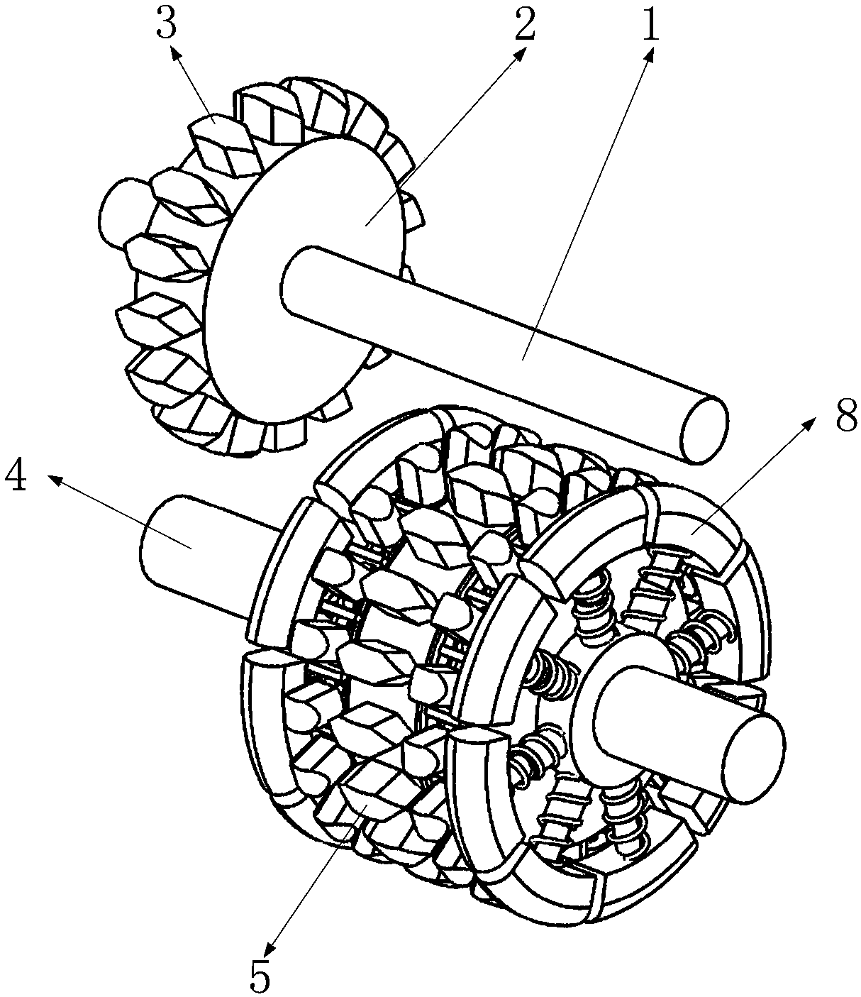
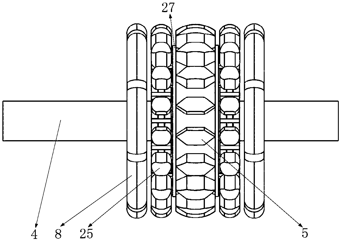
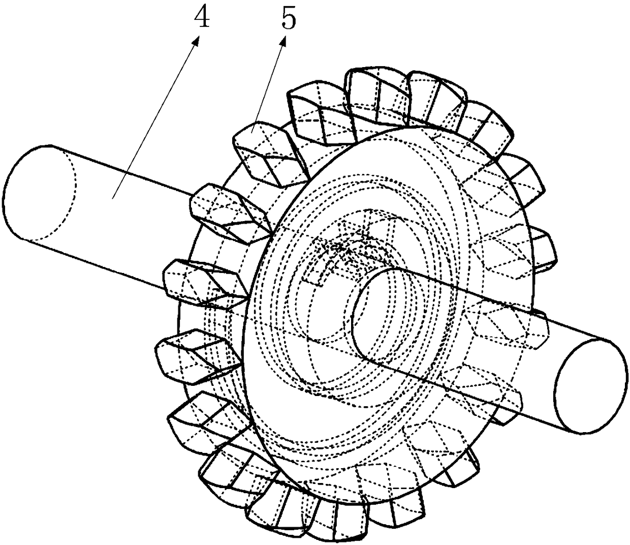
[0090] Specific embodiments: when the driving shaft 4 is not started to rotate, the shifting plate 12 is located in the middle of the two limit plates 10; when the telescopic rod 18 is not compressed, the distance from the outer arc surface of the arc-shaped plate 20 to the axis of the driving shaft 4 It is equal to the distance from the transition circular surface 13 of the driving gear 5 to the axis of the driving shaft 4; when the driving gear 6 is not rotating, the soft tooth 31 is located in the middle of two adjacent fixing plates 28.

[0091] When the driving shaft 4 starts to rotate under the driving of the power unit, the shaft sleeve 7 rotates with the driving shaft 4, and the driving mechanism 8 rotates with the shaft sleeve 7; , then the scroll spring 9 is slightly compressed, and the driving shaft 4 drives the driving gear 6 to rotate through the scroll spring 9. At this time, in the synchronous rotation of the driving shaft 4 and the driving gear 6, the dial 12 is...


PUM


Abstract

The invention belongs to the technical field of gear transmission and particularly relates to a synchronous tooth collision prevention gear transmission mechanism. The gear transmission mechanism comprises a driven shaft, a driven gear, driven teeth, a driving shaft, driving teeth, a driving gear and the like, wherein a driving mechanism is matched with the driven gear to make the rotational speedof the driven gear close to the rotational speed of the driving gear, and rigid collision between the driving gear and the driven gear during engagement of the driving gear and the driven gear is reduced; a synchronization mechanism is matched with the driven gear to make the driven gear and the driving gear rotate synchronously, and rigid collision of the driving gear and the driven gear duringengagement of the driving gear and the driven gear is avoided; besides, when slight rigid collision happens during engagement of the driving teeth and the driven teeth, a volute spiral spring can achieve a certain rigid collision buffering effect. Through the design, the tooth collision phenomenon caused by rigid collision during gear engagement is avoided, and the service life of the gears is prolonged. The synchronous tooth collision prevention gear transmission mechanism is simple in structure and has a good using effect.

Description

technical field [0001] The invention belongs to the technical field of gear transmission, and in particular relates to a gear transmission mechanism for synchronous anti-cutting teeth. Background technique [0002] At present, traditional gear transmission is generally divided into sliding meshing gear transmission and non-sliding meshing gear transmission. The teeth of the gears mesh with each other, so that the driving gear will drive the driven gear to rotate; Not synchronous, so there will be the phenomenon of tooth beating; when the tooth beating is serious, it is easy to damage the teeth, which will affect the meshing transmission between the driving gear and the driven gear; in order to avoid the phenomenon of tooth beating, it is necessary to design a preventive gear. Toothed gear drive mechanism. [0003] The present invention designs a synchronous anti-snaking gear transmission mechanism to solve the above problems. Contents of the invention [0004] In order ...

Claims


Application Information

Patent Timeline
Patent Type & Authority Applications(China)
IPC IPC(8): F16H1/06F16H55/17F16H55/10F16H55/14
CPCF16H1/06F16H55/10F16H55/14F16H55/17F16H2055/178
Inventor 黄玉燕李创英
Owner HAIMEN MAOFA ART DESIGN CO LTD
Why Eureka
Try Eureka