Auto-cascade condensing unit

A condensing unit, self-cascading technology, applied in refrigerators, compressors, steam condensation, etc., can solve problems affecting system stability and safety, many explosion-proof electrical instruments, complex systems, etc., to improve equipment utilization, The effect of compact structure and simple system

Pending Publication Date: 2018-09-28
GUANGDONG SHENLING ENVIRONMENT SYST CO LTD
View PDF4 Cites 0 Cited by
  • Summary
  • Abstract
  • Description
  • Claims
  • Application Information

AI Technical Summary

Problems solved by technology

However, the traditional method is to use four compressors or three compressors alone to achieve three temperature gradients through the classic cascade method. The system is extremely complex and there are many explosion-proof electrical instruments, which affects the stability of the system and safety

Method used


Image

  • Auto-cascade condensing unit
  • Auto-cascade condensing unit

Examples


Embodiment 1

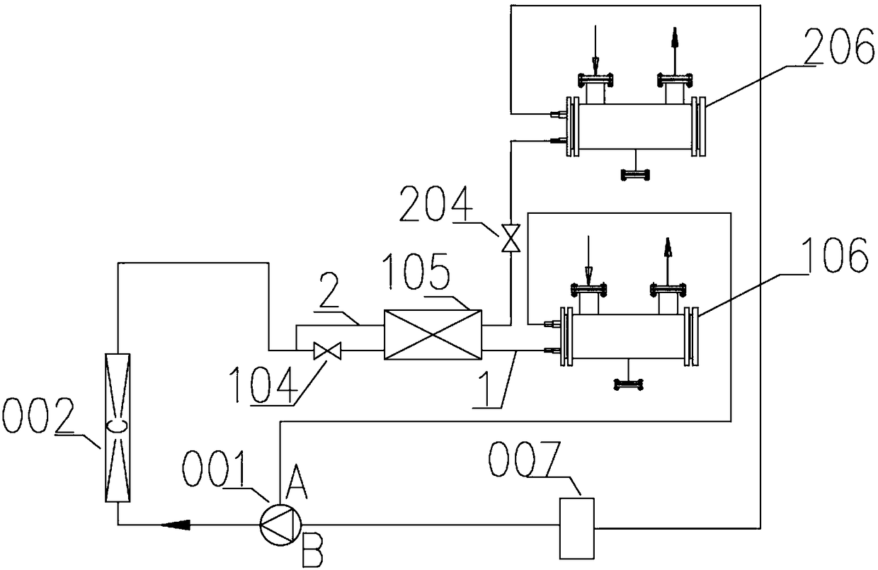
[0039] Such as figure 1 A self-cascading condensing unit shown includes:

[0040] Compressor 001, which is used to provide power and system pressure difference for refrigerant flow;

[0041] Condenser 002, which is connected to compressor 001, and is used to dissipate heat from the refrigerant flowing out of compressor 001;

[0042] A refrigerant classifying device, which is connected to the condenser 002, and is used to classify the refrigerant flowing out of the condenser 002 into various temperature levels;

[0043] The heat exchange terminal is respectively connected with the refrigerant classifying device and the compressor 001, and is used for exchanging heat with the outside using the refrigerant flowing out of the refrigerant classifying device;

[0044] The invention divides the temperature of the refrigerant into multiple different levels through the refrigerant grading device, and only needs one compressor 001 to form multiple temperature gradients at the end of t...

Embodiment 2

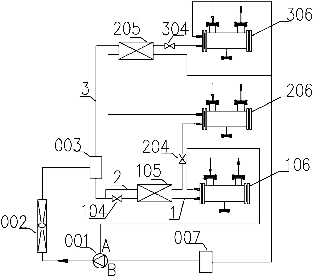
[0059] Such as figure 2 A self-cascading condensing unit shown includes:

[0060] Compressor 001, which is used to provide power for refrigerant flow;

[0061] Condenser 002, which is connected to compressor 001, and is used to dissipate heat from the refrigerant flowing out of compressor 001;

[0062] A refrigerant classifying device, which is connected to the condenser 002, and is used to classify the refrigerant flowing out of the condenser 002 into various temperature levels;

[0063] The heat exchange terminal is respectively connected with the refrigerant classifying device and the compressor 001, and is used for exchanging heat with the outside using the refrigerant flowing out of the refrigerant classifying device;

[0064] The invention divides the temperature of the refrigerant into multiple different levels through the refrigerant grading device, and only needs one compressor 001 to form multiple temperature gradients at the end of the heat exchange for condensat...


PUM


Abstract

The invention particularly relates to an auto-cascade condensing unit. The auto-cascade condensing unit comprises a compressor, a condenser, a refrigerant grading device and a heat exchange terminal,wherein the compressor is used for providing motive power for flowing of a refrigerant; the condenser is connected with the compressor and used for dissipating heat of the refrigerant which flows outof the compressor; the refrigerant grading device is connected with the condenser and used for dividing refrigerant flowing out of the condenser into multiple temperature grades; the heat exchange terminal is connected with the refrigerant grading device and the compressor and used for performing heat exchange with the outside through refrigerant flowing out of the refrigerant grading device; andrefrigerant flowing out of the heat exchange terminal is sucked by the compressor. The temperature of the refrigerant is divided into multiple different grades through the refrigerant grading device,multiple temperature gradients can be formed at the heat exchange terminal for condensing through only one compressor, a complex system is avoided, the potential safety hazard which is prone to occurring due to arrangement of multiple operation equipment is avoided, and the anti-explosion safety and system stability are improved.

Description

technical field [0001] The invention relates to the technical field of oil and gas recovery systems, in particular to a self-cascading condensing unit. Background technique [0002] To meet the oil and gas discharge standards stipulated by the state, oil and gas recovery and treatment devices must be installed to recover and process the light hydrocarbon components in oil and gas. The existing oil and gas treatment methods include condensation, absorption, adsorption and membrane methods. Among them, the condensation method is indispensable as a high-concentration pretreatment process in the oil and gas recovery process. At present, the continuous in-depth research on the condensation temperature and condensation stages through the condensation method has concluded that the oil and gas can be condensed in three stages for oil and gas recovery. When When the condensation temperature is 5°C, -30°C, -70°C, the efficiency and recovery effect are better. However, the traditional...

Claims


Application Information

Patent Timeline
Patent Type & Authority Applications(China)
IPC IPC(8): F25B7/00B01D5/00
CPCB01D5/0036B01D5/0075F25B7/00
Inventor 魏娟梁杰荣王建辉
Owner GUANGDONG SHENLING ENVIRONMENT SYST CO LTD
Why Eureka
Try Eureka