Floor heating pipeline cleaning machine

A technology for pipe cleaning and floor heating pipes, which is applied in the directions of flushing, cleaning heat transfer devices, lighting and heating equipment, etc., can solve problems such as the reduction of heat exchange efficiency, and achieve the effects of saving electric energy, high work efficiency and wide application range.

Pending Publication Date: 2018-09-28
安建林
View PDF0 Cites 1 Cited by
  • Summary
  • Abstract
  • Description
  • Claims
  • Application Information

AI Technical Summary

Problems solved by technology

When the water passes through the heat exchange pipe, the dirt in the water will slowly accumulate inside the pipe wall, which will gradually reduce the heat exchange efficiency.

Method used


Image

  • Floor heating pipeline cleaning machine
  • Floor heating pipeline cleaning machine
  • Floor heating pipeline cleaning machine

Examples


Embodiment Construction

[0018] The present invention will be described in further detail below in conjunction with the accompanying drawings.

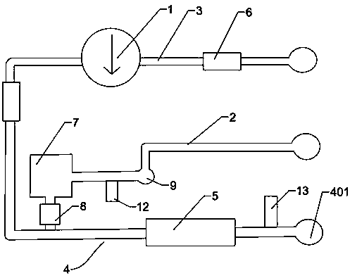
[0019] combined with Figure 1~4 , a floor heating pipe cleaning machine of the present invention, including an air compressor, and a self-priming water pump 1, the air compressor is connected to the air inlet pipe 2, the self-priming water pump 1 is connected to the water inlet pipe 3, the air inlet pipe 2 and the water inlet pipe 3 They are connected in parallel, and the two are connected to the output pipeline 4 through a three-way valve. The output pipeline 4 is provided with a rotating device 5, and the rotating device 5 includes a round tube 501 and a helical blade 502 inside the round tube 501.

[0020] Both ends of the self-priming water pump 1 and located on the water inlet pipe 3 are respectively provided with a check valve-6. The output pipeline 4 is provided with an electromagnetic normally closed valve 7, and the two ends of the electromagnetic ...


PUM


Abstract

The invention relates to a floor heating pipeline cleaning machine. The floor heating pipeline cleaning machine comprises an air compressor and further comprises a self-priming water pump; the air compressor is connected with an air inlet pipeline; the self-priming water pump is connected with a water inlet pipeline; the air inlet pipeline is in parallel connection with the water inlet pipeline; the air inlet pipeline and the water inlet pipeline are connected with an output pipeline through a three-way valve; and a rotating device is arranged on the output pipeline and comprises a round pipeand a spiral blade which is located in the round pipe. The floor heating pipeline cleaning machine adopts a spiral wave cleaning principle, and the rotating device is disposed in the floor heating pipeline cleaning machine, so that the cleaning efficiency of the cleaning machine is higher; and a manual operation mode and a remote operation mode are arranged, equipment braking is achieved in an emergency, remote control over equipment can be achieved, and the floor heating pipeline cleaning machine is convenient to use, easy to manufacture and capable of being widely popularized in the field ofcleaning devices.

Description

technical field [0001] The invention relates to the technical field of cleaning devices, in particular to a floor heating pipeline cleaning machine. Background technique [0002] At present, with the development of industry and the improvement of the quality of life of residents, the heating of residential areas has gradually changed from air-conditioning heating to central heating, such as floor heating heating. When floor heating equipment is in operation, it mainly heats residential buildings by convective heat exchange through high-temperature water flowing through heat exchange pipes. When water passes through the heat exchange pipe, the dirt in the water will slowly accumulate inside the pipe wall, which will gradually reduce the heat exchange efficiency. Therefore, it is necessary to regularly clean the heat exchange pipes. The existing cleaning technology is mainly pulse cleaning. During cleaning, high-pressure air and cleaning water are used to clean the dirt on th...

Claims


Application Information

Patent Timeline
Patent Type & Authority Applications(China)
IPC IPC(8): F28G9/00F28G15/00
CPCF28G9/00F28G15/00F28G15/003
Inventor 安建林
Owner 安建林
Why Eureka
Try Eureka