
Device and method for eliminating edge scattering

An edge and square technology, applied in the field of aircraft stealth, can solve the problems of unrealized edge scattering reduction, difficult processing of gradient resistance resistors, limited resistance variation range, etc., to reduce radar cross section, efficient RCS, reduce Effects of RCS

Inactive Publication Date: 2018-09-28
SHAANXI SCI TECH UNIV
View PDF3 Cites 0 Cited by
  • Summary
  • Abstract
  • Description
  • Claims
  • Application Information

AI Technical Summary

Problems solved by technology

However, how much role the gradient impedance strip plays in it, specifically whether the absorbing foam or the gradient impedance strip plays a leading role in eliminating edge scattering, is not analyzed in Document 2
Document 2 shows that loading impedance strips with gradual resistance on the edge can reduce edge scattering, but the processing of the resistance strip with gradual resistance is difficult, and the range of resistance value variation is limited, which limits its practical application
At the same time, Document 2 only achieves RCS reduction at a single frequency point of 4GHz, but does not achieve edge scattering reduction in the wide frequency range of 1~18GHz

Method used


Image

  • Device and method for eliminating edge scattering
  • Device and method for eliminating edge scattering
  • Device and method for eliminating edge scattering

Examples


Embodiment Construction

[0027] In order to make the object, technical solution and advantages of the present invention clearer, the present invention will be further described in detail below in conjunction with the accompanying drawings and embodiments. It should be understood that the specific embodiments described here are only used to explain the present invention, not to limit the present invention.

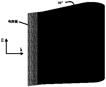
[0028] Such as figure 1 as shown, figure 1 It is a structural schematic diagram of the device for eliminating edge scattering in the embodiment of the present invention.

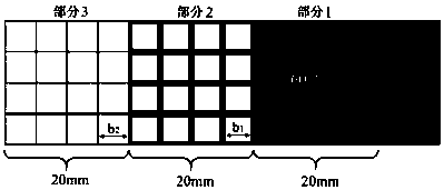
[0029] The invention discloses a device for eliminating edge scattering. The device includes a wedge, and a resistance plate is arranged on the edge of the tip of the wedge, and the resistance plate includes a fully coated resistance area and several grid-coated resistance areas. ; The full-coated resistance area and each grid-coated resistance area are sequentially connected in a side-by-side manner away from the sharp edge of...


PUM


Abstract

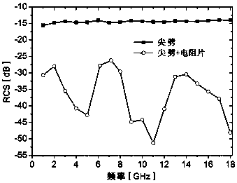
The invention discloses a device and method for eliminating edge scattering. The device comprises a wedge, and a resistance plate is arranged on a tip-end edge of the wedge and comprises a full-coatedresistance region and a plurality of grid-coated resistance regions; the full-coated resistance region and the grid-coated resistance regions are sequentially connected side by side in the directionof being far away from the tip-end edge of the wedge; the full-coated resistance region is fully coated with a resistance material, and the grid-coated resistance regions are coated with grids including multiple sub-grids by taking a resistance material as grid lines; the full-coated resistance region is directly connected with the tip-end edge of the wedge; and the regions of grids in the grid-coated resistance regions are same, and the blank region areas, located in the grid lines, of the sub-grids of the grid-coated resistance regions are gradually increased in the direction of being far away from the tip-end edge of the wedge. The device can significantly reduce RCS caused by edge scattering within the range of 1-18 GHz and is simple in structure and suitable for practical application.

Description

technical field [0001] The invention belongs to the technical field of aircraft stealth, and in particular relates to a device and method for eliminating edge scattering. Background technique [0002] There are several scattering sources on a scatterer, and different types of scattering sources have different contributions to the radar cross section of the scatterer. According to the magnitude of the echo intensity, the common scattering sources are specular reflection, edge scattering, traveling wave echo, crawling wave echo, peak diffraction, surface contour discontinuity and so on. Edge scattering is the second most powerful source of scattering after specular reflection. [0003] Eliminating edge scattering has important practical significance. For example, there are hundreds of edges on an aircraft. If the edges are not handled properly, it will seriously affect the stealth capability of the aircraft. Some researchers have already carried out research on this. For ex...

Claims


Application Information

Patent Timeline
Patent Type & Authority Applications(China)
IPC IPC(8): F41H3/00
CPCF41H3/00
Inventor 方俊飞陈正涛张鹏超
Owner SHAANXI SCI TECH UNIV
Learn More