An integrated aircraft fuselage with skin antenna

An aircraft fuselage and fuselage technology, applied in the direction of fuselage, fuselage frame, aircraft parts, etc., can solve the problems of reducing the accuracy of airborne electronic equipment, low system rigidity, poor flatness, etc., and achieve the increase of payload weight, The effect of reducing flight cost and increasing flight time

Active Publication Date: 2022-04-29
CHINA ELECTRONIC TECH GRP CORP NO 38 RES INST
View PDF0 Cites 0 Cited by
  • Summary
  • Abstract
  • Description
  • Claims
  • Application Information

AI Technical Summary

Problems solved by technology

This structure is similar to the series connection of multiple systems, and since the rigidity of the installation structures such as the hanging warehouse, the disc, and the balance beam cannot be made too high, this will result in a low rigidity of the entire system
The system stiffness is low, and the flatness of the antenna will be poor under the vibration of the aircraft, which will reduce the accuracy of the airborne electronic equipment

Method used


Image

  • An integrated aircraft fuselage with skin antenna
  • An integrated aircraft fuselage with skin antenna
  • An integrated aircraft fuselage with skin antenna

Examples


Embodiment

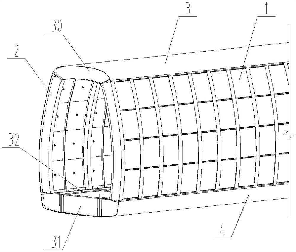
[0046] see figure 1 , an integrated aircraft fuselage with a skin antenna includes a left fuselage side wall mechanism 1, a right fuselage side wall mechanism 2, a fuselage top wall plate 3 and a fuselage bottom wall plate 4; the left fuselage side wall mechanism 1 and the right fuselage side wall mechanism 2 have the same structure; the left fuselage side wall mechanism 1 is composed of several fuselage side wall units arranged and connected horizontally.

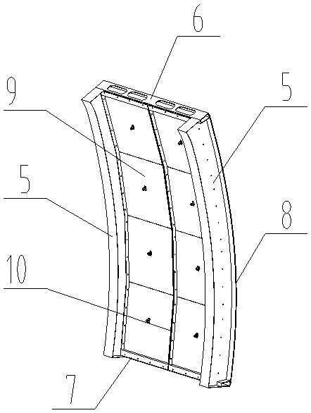
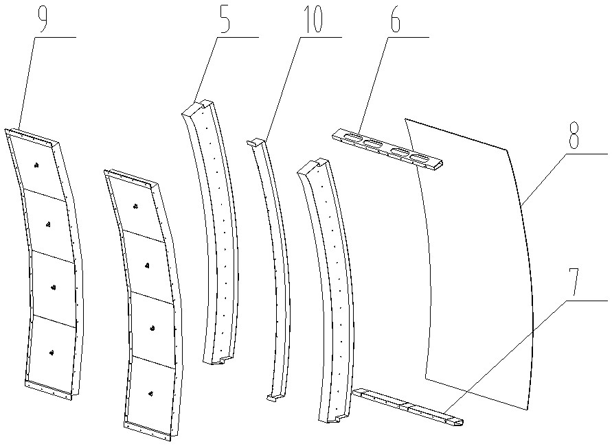
[0047] see figure 2 and image 3 , the fuselage side wall unit comprises a pair of rod-shaped fuselage frame edges 5, an upper truss 6 and a lower truss 7 fixedly connected to form a fuselage frame, and an outer fuselage panel 8 is installed on the outer side of the fuselage frame, Two groups of antenna unit groups 9 are evenly distributed on the inner surface of the fuselage frame, and each group of antenna unit groups 9 includes four antenna units; The upper end is fixedly connected to the upper girder 6, and the low...


PUM


Abstract

The invention relates to an integrated aircraft fuselage with a skin antenna, and belongs to the field of radar platform load integrated design. Including the left fuselage side wall mechanism, right fuselage side wall mechanism, fuselage top wall plate and fuselage bottom wall plate; the structure of the fuselage mechanism on both sides is the same; each side fuselage side wall mechanism consists of several fuselage side wall units Horizontally arranged and connected; the fuselage side wall unit includes a fuselage frame composed of a pair of rod-shaped fuselage frame edges, upper girders and lower girders. Two sets of antenna unit groups are evenly distributed on the inner surface of the frame, and each group of antenna unit groups includes more than three antenna units; it forms an integrated skin antenna array conformal to the fuselage; several antenna unit groups connect ribs , The upper truss and the lower truss form an electrical connection to form an antenna front. The antenna array of the present invention does not require additional support structures such as hanging bins, discs, and balance beams, and the load weight can be reduced by about 12%.

Description

technical field [0001] The invention belongs to the field of radar platform load integration design, and in particular relates to an aircraft fuselage with an integrated design of aircraft fuselage skin and radar antenna structure, which is mainly used in sensor aircraft or platform load integrated aircraft platforms. Background technique [0002] As an important part of electronic equipment, the antenna array is usually composed of a large number of antenna elements in a certain array, which mainly emits and receives various electromagnetic waves. Now all kinds of airborne detection, communication, and surveying and mapping electronic equipment contain a large number of antenna arrays. [0003] In traditional airborne electronic equipment, these antenna arrays are usually installed on the nose of the aircraft, inside the fuselage, or suspended at the bottom of the belly in the form of a pod, or installed on the back of the fuselage in the form of a disc or balance beam. . ...

Claims


Application Information

Patent Timeline
Patent Type & Authority Patents(China)
IPC IPC(8): B64C1/06B64C1/36
CPCB64C1/061B64C1/064B64C1/068B64C1/36Y02T50/40
Inventor 彭超张平杨双根程林杨静王平安郭琳李凤英高山陈声麒黄小庆霍恩来
Owner CHINA ELECTRONIC TECH GRP CORP NO 38 RES INST
Why Eureka
Try Eureka