
A Wide Angle Circularly Polarized Metasurface Antenna

A metasurface, wide-angle technology, used in antennas, antenna arrays, antenna grounding devices, etc., can solve the problem of wide-angle circular polarization not being realized, achieve good circular polarization function, and expand the application range.

Inactive Publication Date: 2019-04-16
NANJING UNIV OF AERONAUTICS & ASTRONAUTICS
View PDF1 Cites 0 Cited by
  • Summary
  • Abstract
  • Description
  • Claims
  • Application Information

AI Technical Summary

Problems solved by technology

[0004] A series of research results have shown that it is relatively easy to use metasurfaces to realize circular polarization, especially broadband circular polarization, but wide-angle circular polarization has hardly been realized.

Method used


Image

  • A Wide Angle Circularly Polarized Metasurface Antenna
  • A Wide Angle Circularly Polarized Metasurface Antenna
  • A Wide Angle Circularly Polarized Metasurface Antenna

Examples


Embodiment 1

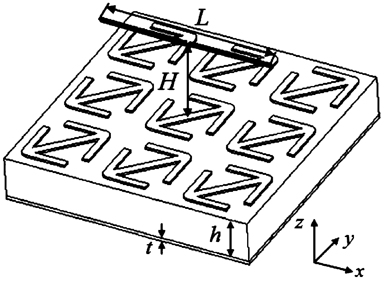
[0029] Such as figure 1 As shown, the wide-angle circularly polarized metasurface antenna consists of two parts. The first part is the metasurface structure, which is composed of nine identical metasurface units with a square cross-section arranged in a three-by-three manner without gaps, and the periods along the x and y directions are both p=12 mm. The metasurface unit is composed of a dielectric substrate, a ground plate arranged on one surface of the dielectric substrate, and a double-arrow-shaped metal patch arranged on the other surface of the dielectric substrate. The thickness of the dielectric substrate is h=6 mm, and the thickness of the ground plate and the metal patch is t=0.018 mm. The second part is a traditional half-wavelength dipole antenna with a length of L=25 mm, placed directly above the metasurface structure, and a vertical height H=8 mm above the metasurface;

Embodiment 2

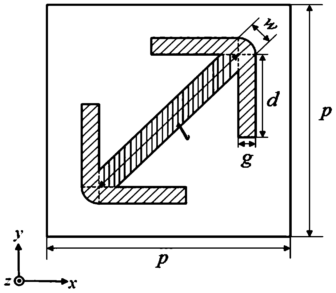
[0031] As shown in Figure 2, the structure is a metasurface unit. The metal patch in the shape of a double arrow is composed of a metal strip in the middle and an "L"-shaped metal patch that is symmetrical at both ends of the metal strip. The entire metal patch structure is along the opposite sides of the metasurface unit. The diagonals are placed and are symmetrical about both diagonals (symmetrical about the center of the metasurface element). The length of the metal strip is l=10 mm, the width w=1.2 mm, the length d=5.7 mm, and the width g=1 mm of the symmetrical "L"-shaped metal patch at both ends.

[0032] Such as image 3 Shown is the reflection coefficient of the metasurface structure. It can be found that the C-band co-polarization reflection coefficient is below -15dB, and the cross-polarization reflection coefficient is close to 0dB, realizing a high-efficiency polarization conversion function. In addition, the effective working frequency band of the metasurface str...


PUM


Abstract

The invention provides a wide-angle circularly-polarized super surface antenna comprising a super surface structure and a half-wavelength dipole antenna placed at a certain height right above the super surface structure. The super surface structure is formed by periodically extending super surface units in the x and y directions according to a certain period respectively, and a super surface unit m*n gap-free arrangement structure is formed, wherein m and n are natural numbers greater than or equal to 2. Each super surface unit is composed of a dielectric substrate, a grounding plate arranged on one side of the dielectric substrate, and a double-arrow-shaped metal patch arranged on the other side of the dielectric substrate. According to the invention, circularly-polarized radiation wave can be generated in a space above the dipole antenna, and by changing the sizes of the super surface units and the dipole antenna and the vertical distance between the super surface units and the dipole antenna, the super surface antenna is enabled to work in different frequency bands. The wide-angle circularly-polarized super surface antenna of the invention has a series of advantages of simple structure, easy frequency adjustment, wide circular polarization angle, radar scattering cross section reduction, and the like.

Description

technical field [0001] The invention relates to an antenna structure, in particular to a wide-angle circularly polarized metasurface antenna structure. Background technique [0002] Metamaterials are usually new artificial electromagnetic materials composed of periodic or non-periodic arrangements of subwavelength basic units with specific geometric shapes, and have properties that materials in nature do not have. The metasurface can be equivalent to a two-dimensional metamaterial, which has a strong ability to control electromagnetic waves, and can realize functions such as polarization conversion and polarization rotation. Not only that, the application of metasurfaces in antenna design can improve the performance of traditional antennas in terms of operating bandwidth, directivity, radiation efficiency, gain, etc. This new type of antenna designed by combining metasurface structures with traditional antennas It can be called a metasurface antenna. Chung, K. et al. propo...

Claims


Application Information

Patent Timeline
Patent Type & Authority Patents(China)
IPC IPC(8): H01Q1/38H01Q1/48H01Q15/24H01Q21/00
Inventor 李茁陈晨刘亮亮徐佳王婷婷许秉正陈新蕾顾长青
Owner NANJING UNIV OF AERONAUTICS & ASTRONAUTICS
Learn More