
Applied electric field-induced friction device and testing method thereof

A technology of friction device and external electric field, which is applied in the field of friction device, can solve the problems such as the friction coefficient is difficult to reach a very low friction stage, low friction coefficient, etc.

Active Publication Date: 2018-09-28
SHENZHEN UNIV
View PDF7 Cites 3 Cited by
  • Summary
  • Abstract
  • Description
  • Claims
  • Application Information

AI Technical Summary

Problems solved by technology

[0002] The pursuit of low friction or even zero friction has always been a hot topic in tribology research. As a typical anti-friction coating material, carbon materials have high hardness, low friction coefficient, and high wear resistance. The friction coefficient can be as low as 0.01~0.1, and the surface that usually rubs against carbon materials is a surface with less roughness, such as ceramics; but for metal surfaces, the friction coefficient is difficult to reach a very low friction stage

Method used


Image

  • Applied electric field-induced friction device and testing method thereof
  • Applied electric field-induced friction device and testing method thereof
  • Applied electric field-induced friction device and testing method thereof

Examples


Embodiment Construction

[0025] In order to make the object, technical solution and advantages of the present invention more clear and definite, the present invention will be further described in detail below with reference to the accompanying drawings and examples. It should be understood that the specific embodiments described here are only used to explain the present invention, not to limit the present invention.

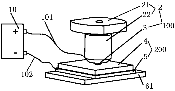
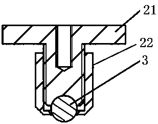
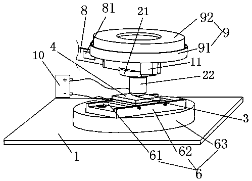
[0026] Please also see Figure 1-Figure 7 . The invention provides a friction device induced by an external electric field, such as Figure 1-Figure 4 As shown, it includes a base 1, an upper friction pair 100 composed of a conductive fixture 2 and a metal friction member 3 arranged at the bottom of the conductive fixture 2, a carbon-based film 4 and a friction pair 100 arranged at the bottom of the carbon-based film 4 The lower friction pair 200, the moving unit 6, the adjusting unit 7, the strain beam 8, the loading unit 9, the cantilever beam 11 and the power supply 10 composed of t...


PUM


Abstract

The invention discloses an applied electric field-induced friction device and a testing method thereof. The applied electric field-induced friction device comprises a pedestal, an upper friction pairscomposed of a conductive clamp and a metal friction piece arranged at the bottom of the conductive clamp, a lower friction pairs composed of a carbon based film and a plate electrode arranged at thebottom of the carbon based film, and a motion unit and an adjusting unit arranged at the pedestal, a strain beam, a loading unit, a cantilever beam, and a power source which are arranged at the pedestal. The motion unit pushes the lower friction pairs to move, a strain sheet is arranged at the strain beam, the front bottom of the cantilever beam is connected with the upper friction pairs, the topof the front end of the cantilever beam is connected with the loading unit, the rear end of the cantilever beam is connected with the front end of the strain beam, the adjusting unit is connected withthe rear end of the strain beam, the position of the upper friction pairs is adjusted, a positive pole of the power source is electrically connected with the conductive clamp, a negative pole of thepower source is electrically connected with a plate electrode, so that the friction coefficient between the metal friction piece and the carbon based film is reduced.

Description

technical field [0001] The invention relates to the technical field of friction devices, in particular to a friction device induced by an external electric field and a testing method thereof. Background technique [0002] The pursuit of low friction or even zero friction has always been a hot topic in tribology research. As a typical anti-friction coating material, carbon materials have high hardness, low friction coefficient, and high wear resistance. The friction coefficient can be as low as 0.01~0.1, and the surface that usually rubs against carbon materials is a surface with less roughness, such as ceramics; but for metal surfaces, the friction coefficient is difficult to reach a very low friction stage. [0003] Therefore, the prior art still needs to be improved and developed. Contents of the invention [0004] The technical problem to be solved by the present invention is to provide a friction device induced by an external electric field and a testing method thereo...

Claims


Application Information

Patent Timeline
IPC IPC(8): G01N19/02
CPCG01N19/02
Inventor 刁东风孙锟
Owner SHENZHEN UNIV
Learn More