
Photoelectric integrated intelligent optical fiber adaptation system

A technology of intelligent optical fiber and adaptation system, applied in the direction of light guides, optics, optical components, etc., can solve the difficulties in realizing the real-time management and maintenance of optical fiber adaptation nodes, the difficulty in establishing and managing optical distribution systems, and increasing the difficulty of on-site construction operations, etc. problems, achieve the effect of realizing intelligent management, simple and reliable process and structure, and improving operability

Active Publication Date: 2018-09-28
FENGHUO COMM SCI & TECH CO LTD
View PDF10 Cites 4 Cited by
  • Summary
  • Abstract
  • Description
  • Claims
  • Application Information

AI Technical Summary

Problems solved by technology

However, in the face of a huge optical communication network, this method is inefficient
It is difficult to realize the real-time management and maintenance of the increasingly large fiber adapter nodes by manual recording
In the case of artificial memory error or damaged label, the corresponding relationship between each adapter node and user in the optical distribution network will be confused, which will cause difficulties in the establishment and management of the optical distribution system
[0005] Nowadays, electronic labels are also used to display the occupancy of fiber optic adapters, and electronic labels can accurately reflect the occupancy of optical fiber adapters; however, since the electronic labels and adapters are separated, the electronic labels need to be fixed on the adapters during installation, which increases the on-site The difficulty of operation during construction increases the burden of material preparation for installation and increases the cost of production and installation

Method used


Image

  • Photoelectric integrated intelligent optical fiber adaptation system
  • Photoelectric integrated intelligent optical fiber adaptation system
  • Photoelectric integrated intelligent optical fiber adaptation system

Examples


no. 1 example

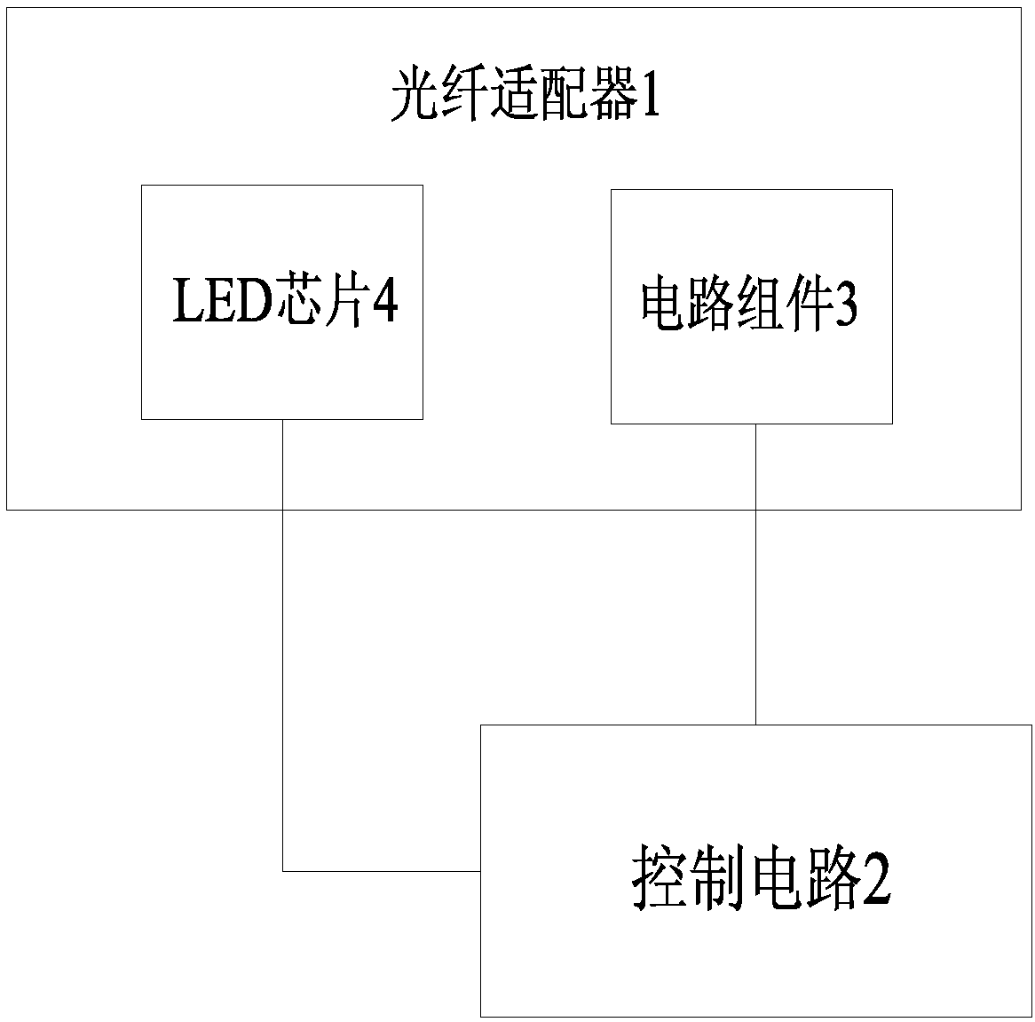
[0049] Such as figure 1 , image 3 and Figure 4 As shown, the optoelectronic integrated intelligent optical fiber adaptation system of the present invention includes an optical fiber adapter 1 and an external control circuit 2. The optical fiber adapter 1 is equipped with an LED chip 4 and a circuit assembly 3, and the circuit assembly 3 is electrically connected to the LED chip 4 respectively. and control circuit 2.

[0050] When the optical fiber adapter 1 is not connected to the optical fiber connector, a closed circuit is formed among the circuit assembly 3 , the control circuit 2 and the LED chip 4 , and the LED chip 4 emits light.

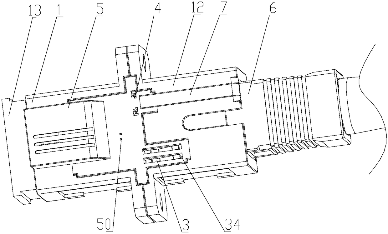
[0051] When the optical fiber adapter 1 is docked with the optical fiber connector 6, the electrical signal of the circuit assembly 3 is disconnected, and the LED chip 4 does not emit light.

no. 2 example

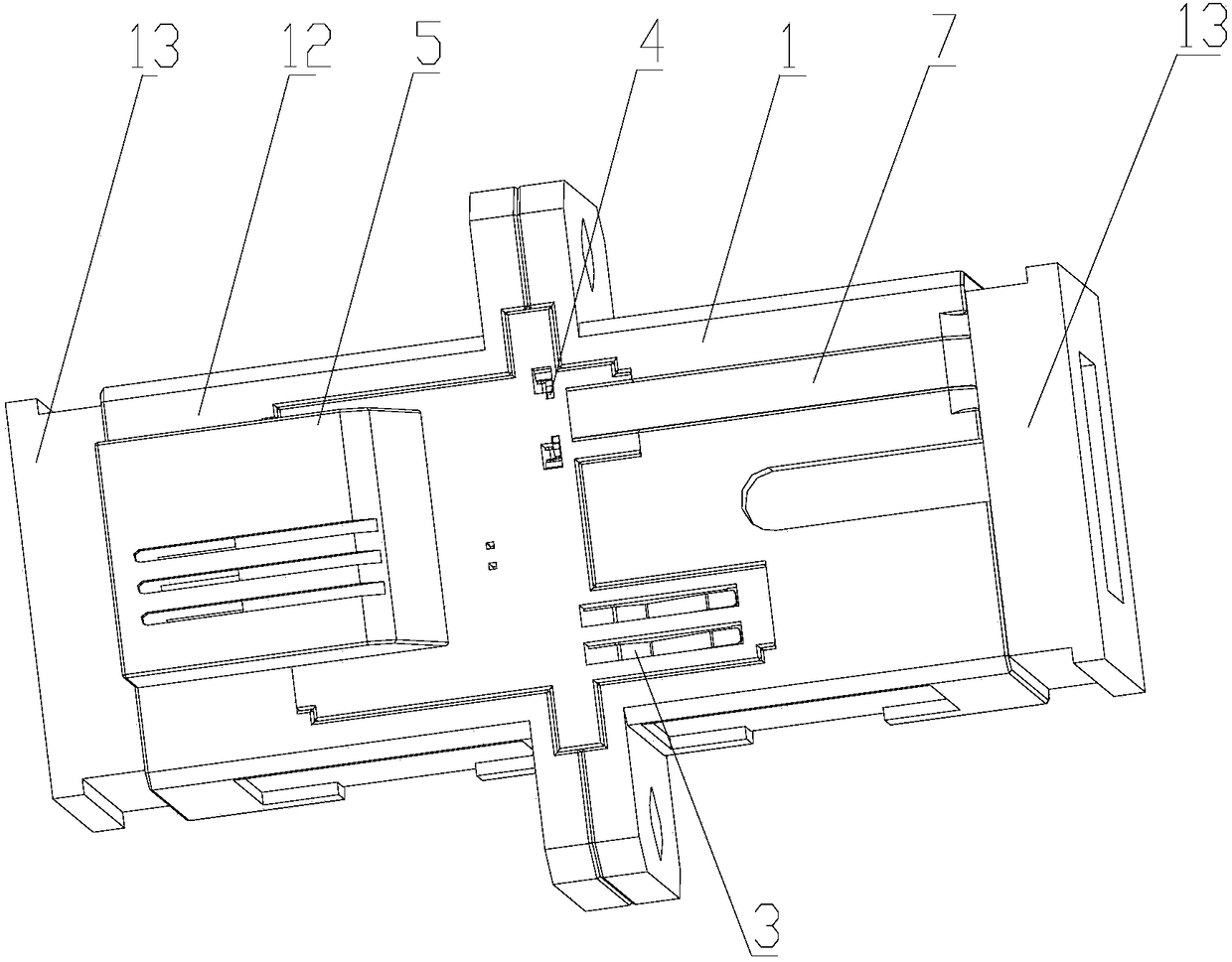
[0053] Such as Figure 2 to Figure 4 As shown, on the basis of the above embodiments, the LED chip 4 and the circuit assembly 3 are installed in a plastic seat 5 , and the plastic seat 5 is arranged on the surface of the optical fiber adapter 1 .

[0054] Such as Figure 9 As shown, the two ends of the LED chip 4 are a positive electrode 41 and a negative electrode 42 respectively, and the middle part of the LED chip 4 protrudes to form a light-emitting surface 43 , which is higher than the positive electrode 41 and the negative electrode 42 .

[0055] Such as Figure 8 and Figure 9 As shown, the circuit assembly 3 includes an LED control terminal 31, a common terminal 32 and a feedback terminal 33, and each terminal has a pin connected to the control circuit 2. In this embodiment, the three pins are LED control terminal pins respectively 310 , common terminal pin 320 and feedback terminal pin 330 . The common terminal 32 has two connecting arms, namely the first connecti...

no. 3 example

[0060] This embodiment is based on the second embodiment, such as figure 2 , Figure 5 , Figure 6 and Figure 7 As shown, the plastic seat 5 includes a base plate 51 , and a protruding portion 52 is arranged on the base plate 51 , and a pin interface 53 is formed inside the protruding portion 52 . The plastic seat 5 also includes a first circuit component accommodation groove 54, a second circuit component accommodation groove 55, an LED chip accommodation groove 56 and a conductive sheet accommodation groove 57, and the first circuit assembly accommodation groove 54 and the second circuit assembly accommodation groove 55 are all connected with each other. The pin interface 53 communicates.

[0061] The pin interface 53 extends to the rear end of the optical fiber adapter 1, and is used to insert the gold finger of the control circuit 2, so that the gold finger and the pins of the LED control terminal 31, the common terminal 32 and the feedback terminal 33 are electricall...


PUM


Abstract

The invention discloses a photoelectric integrated intelligent optical fiber adaptation system, and relates to the field of optical fiber adapters. The system comprises an optical fiber adapter and acontrol circuit; an LED chip and a circuit module are installed on the optical fiber adapter, and the circuit module is connected with the control circuit and the LED chip separately; when the opticalfiber adapter is vacant, a closed loop circuit is formed among the circuit module, the control circuit and the LED chip, and the LED chip gives out light; when the optical fiber adapter is in butt joint with an optical connector, an electrical signal of the circuit module is disconnected, and the LED chip does not give out light. By means of flashing on and off of the LED chip on the optical fiber adaptor, the occupancy of the optical fiber adapter is displayed in real time, intelligent management is achieved, and meanwhile the construction difficulty and mounting cost cannot be increased.

Description

technical field [0001] The invention relates to the field of optical fiber adapters, in particular to an optoelectronic integrated intelligent optical fiber adaptation system. Background technique [0002] With the development of society, the demand for communication is increasing. Optical fiber communication has gradually replaced cable and microwave communication as the main information transmission method due to its wide transmission frequency bandwidth, high anti-interference performance and low signal attenuation. In recent years, the optical fiber communication industry has achieved considerable development, and the integration of the three networks has been deepened, setting off an upsurge in the construction of fiber access (Fiber To The x, FTTx) networks. The amount of communication data and the communication speed are constantly increasing, and the passive nature of the FTTx network makes the maintenance and management of the Optical Distribution Network (ODN) more...

Claims


Application Information

Patent Timeline
Patent Type & Authority Applications(China)
IPC IPC(8): G02B6/38
CPCG02B6/3895
Inventor 黄美金李骢王晓峰
Owner FENGHUO COMM SCI & TECH CO LTD
Learn More