Electric reactor iron core pull rod clamping method and structure

A reactor and tie rod technology, applied in transformer/inductor cores, inductors, fixed inductors, etc., can solve the problems of low insulation resistance of iron core clips, equipment accidents, loose structural parts, etc., to eliminate insulation resistance. too low, reducing vibration, reducing the effect of noise

Pending Publication Date: 2018-09-28
BAODING TIANWEI BAOBIAN ELECTRICAL
View PDF7 Cites 0 Cited by
  • Summary
  • Abstract
  • Description
  • Claims
  • Application Information

AI Technical Summary

Problems solved by technology

[0002] The clamping of the reactor core has a great influence on the reactor. The shunt reactor will produce a certain amplitude of vibration during the start-up and operation. If this vibration is not avoided and controlled, it is easy to cause structural parts The looseness of the iron core clamp will cause the insulation resistance of the iron core clamp to be too low, resulting in equipment accidents

Method used


Image

  • Electric reactor iron core pull rod clamping method and structure
  • Electric reactor iron core pull rod clamping method and structure
  • Electric reactor iron core pull rod clamping method and structure

Examples


Embodiment Construction

[0015] Below in conjunction with accompanying drawing, the present invention will be further described by examples.

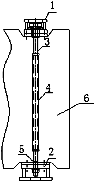
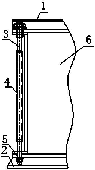
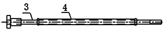
[0016] Refer to attached figure 1 , 2 , 3, a reactor iron core pull rod clamping structure, including support plate 1, pad 2, pull rod 3, copper tube 4, insulating tube 5 and reactor core 6, support plate 1 is located at the reactor core 6 In the upper part, the feet 2 are set at the lower part of the reactor core 6, and the support plate 1, the reactor core 6 and the feet 2 are fixedly clamped and connected by the tie rod 3, and the tie rod 3 is set in the copper tube 4, and the tie rod 3 and the support plate An anti-loosening disc spring is arranged between 1, and an insulating tube 5 is arranged between the pull rod 3 and the feet 2.

[0017] A method for clamping a tie rod of a reactor iron core, adopting the above-mentioned tensioning structure, the steps are as follows: the upper part of the reactor iron core has a support plate 1, and the lower part h...


PUM


Abstract

The invention relates to an electric reactor iron core pull rod clamping method and structure, and belongs to the technical field of the electric reactor equipment. The technical scheme comprises a bracing plate (1), a foot pad (2), a pull rod (3), a copper pipe (4), an insulating pipe (5) and an electric reactor iron core (6); the bracing plate (1) is arranged at the upper part of the electric reactor iron core (6), the foot pad (2) is located at the lower part of the electric reactor iron core (6), the bracing plate (1), the electric reactor iron core (6) and the foot pad (2) are fixed, clamped and connected through the pull rod (3); the pull rod (3) is arranged in the copper pipe (4), an anti-loose disc spring is arranged between the pull rod (3) and the bracing plate (1), and the insulating pipe (5) is arranged between the pull rod (3) and the foot pad (2). The clamping method disclosed by the invention has the advantages that the iron core is clamped by using the iron core external pull rod, the noise of the iron core is reduced, and the vibration of the electric reactor is reduced; and the problem that the equipment accident is caused since the insulation resistance of the iron core clamp is too low due to the loosening of the structural member is eliminated.

Description

technical field [0001] The invention relates to a method and structure for clamping a reactor iron core pull rod, and belongs to the technical field of reactor equipment. Background technique [0002] The clamping of the reactor core has a great influence on the reactor. The shunt reactor will produce a certain amplitude of vibration during the start-up and operation. If this vibration is not avoided and controlled, it is easy to cause structural parts The looseness of the iron core clamp will cause the insulation resistance of the iron core clamp to be too low, resulting in equipment accidents. The reactor cannot clamp the iron core laminations at the center due to the magnetic flux leakage of the iron core. Therefore, it is necessary to clamp the iron core outside the iron core laminations to reduce the noise of the iron core and the reactor vibration. Contents of the invention [0003] The object of the present invention is to provide a method and structure for clampi...

Claims


Application Information

Patent Timeline
Patent Type & Authority Applications(China)
IPC IPC(8): H01F27/26H01F27/33H01F27/36H01F37/00
CPCH01F27/263H01F27/33H01F37/00H01F27/36
Inventor 张永恒张静程从明谢京于素梅徐爽王永强唐晓辉王丽荣
Owner BAODING TIANWEI BAOBIAN ELECTRICAL
Why Eureka
Try Eureka