
A current transformer for 24kv central cabinet

A technology for current transformers and central cabinets, applied in the field of transformers, can solve the problems of increased equipment volume and increased casting materials, and achieve the effects of reducing production cycle, preventing rotation, and reducing curing shrinkage

Active Publication Date: 2020-11-24
SHANGHAI DAYIHU POWER ELECTRICAL APPLIANCE
View PDF11 Cites 0 Cited by
  • Summary
  • Abstract
  • Description
  • Claims
  • Application Information

AI Technical Summary

Problems solved by technology

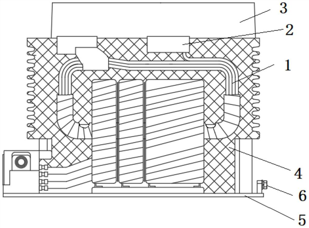
[0003] For high-voltage current transformers, to increase the creepage distance, traditionally, the spacing between conductive parts is usually controlled. For example, this requires controlling the external dimensions of the equipment to a certain extent. The extended distance often leads to an increase in the volume of the equipment and an increase in the use of pouring materials for the equipment.

Method used


Image

  • A current transformer for 24kv central cabinet
  • A current transformer for 24kv central cabinet
  • A current transformer for 24kv central cabinet

Examples


Embodiment Construction

[0040] In order to make the technical means, creative features, goals and effects achieved by the present invention easy to understand, the present invention will be further described below in conjunction with specific diagrams.

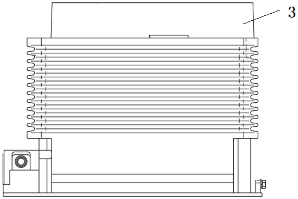
[0041] refer to figure 1 , figure 2 , image 3 , a current transformer used in a 24kV central cabinet, including a current transformer, the current transformer includes an insulating shell 4, a primary connecting terminal 2, and a secondary connecting terminal, the first connecting terminal is located on the top of the insulating shell 4; The two connecting terminals are located on one side of the bottom of the insulating shell 4; the insulating shell 4 includes an upper part and a lower part arranged up and down, the cross-sectional area of ​​the upper part is larger than that of the lower part, and the outer wall of the upper part is provided with at least three longitudinally arranged ring-shaped Groove; also includes a partition 3 made of insu...


PUM


Abstract

The invention relates to the technical field of mutual inductors. A current transformer in a 24 kV centrally installed switchgear comprises a current transformer; the current transformer comprises aninsulating shell, primary connection terminals and secondary connection terminals; the first connection terminals are located at the top part of the insulating shell; the second connection terminals are located at one side of the bottom of the insulating shell; the insulating shell comprises an upper part and a lower part which are arranged in a vertical direction; the cross section area of the upper part is greater than the cross section area of the lower part; at least three annular grooves which are in lengthways arrangement are formed in the outer wall of the upper part; the current transformer further comprises clapboards made of an insulating material; and the clapboards are arranged at the upper part of the insulating shell and are located at the two sides of the primary connectionterminals. Through setting of the orientation of the first connection terminals and the second connection terminals, a creepage distance of the connection terminals is added; in addition, as the clapboards are arranged additionally, the creepage distance between phases is added. Through optimization of the insulating shell, the creepage distance is further increased.

Description

technical field [0001] The invention relates to the technical field of transformers, in particular to current transformers. Background technique [0002] 24kV current transformer is a kind of high voltage current transformer. [0003] For high-voltage current transformers, to increase the creepage distance, traditionally, the spacing between conductive parts is usually controlled. For example, this requires controlling the external dimensions of the equipment to a certain extent. The extended distance often leads to an increase in the volume of the equipment and an increase in the use of pouring materials for the equipment. Contents of the invention [0004] The object of the present invention is to provide a current transformer for use in a 24kV central cabinet to solve at least one of the above technical problems. [0005] The technical problem solved by the present invention can adopt following technical scheme to realize: [0006] A current transformer for use in a ...

Claims


Application Information

Patent Timeline
Patent Type & Authority Patents(China)
IPC IPC(8): H01F38/30H01F27/29H01F27/02H01F27/32H01F27/36H01F27/18H01F27/06
CPCH01F27/02H01F27/022H01F27/025H01F27/06H01F27/18H01F27/29H01F27/321H01F27/324H01F27/36H01F38/30
Inventor 侯罡胡光远王继元沙玉洲郭将军王骞
Owner SHANGHAI DAYIHU POWER ELECTRICAL APPLIANCE
Learn More