
Switching circuit for unmanned aerial vehicle and unmanned aerial vehicle

A technology of switching circuits and drones, applied in the field of switches, can solve problems such as large inrush current, blown fuses, and drones not working properly

Active Publication Date: 2018-09-28
SHENZHEN MICROMULTICOPTER AERO TECH CO LTD
View PDF5 Cites 0 Cited by
  • Summary
  • Abstract
  • Description
  • Claims
  • Application Information

AI Technical Summary

Problems solved by technology

However, as the weight of drones becomes heavier and heavier, the power supply voltage required is also higher and higher
Then, at the moment when the drone is powered on, the surge current flowing into the drone's power supply equipment is very large, which can easily damage the power supply or cause the fuse to blow out, making the drone unable to work normally.

Method used


Image

  • Switching circuit for unmanned aerial vehicle and unmanned aerial vehicle
  • Switching circuit for unmanned aerial vehicle and unmanned aerial vehicle

Examples


Embodiment Construction

[0023] In order to facilitate the understanding of the present invention, the present invention will be described more fully below with reference to the associated drawings. Preferred embodiments of the invention are shown in the accompanying drawings. However, the present invention can be embodied in many different forms and is not limited to the embodiments described herein. On the contrary, these embodiments are provided to make the understanding of the disclosure of the present invention more thorough and comprehensive.

[0024] Unless otherwise defined, all technical and scientific terms used herein have the same meaning as commonly understood by one of ordinary skill in the technical field of the invention. The terminology used herein in the description of the invention is for the purpose of describing specific embodiments only, and is not intended to limit the present invention. As used herein, the term "and / or" includes any and all combinations of one or more of the ...


PUM


Abstract

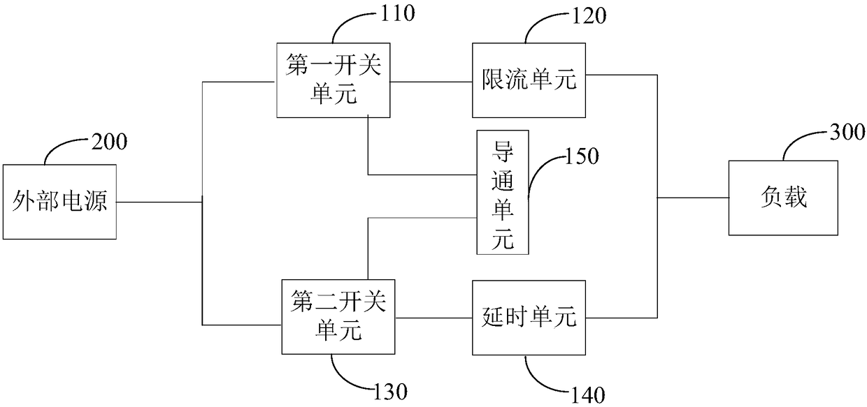
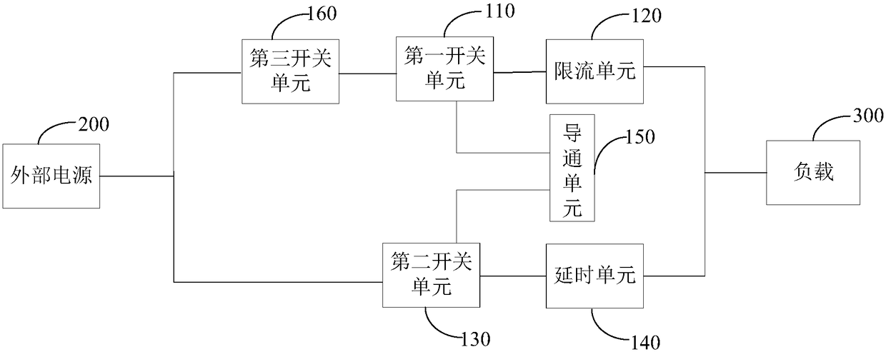
The invention relates to a switching circuit for an unmanned aerial vehicle. The switching circuit comprises a first switching unit, a current limiting unit, a second switching unit and a delay unit,wherein the input end, control end and output end of the first switching unit are correspondingly connected with an external power supply, a conduction unit and one end of the current limiting unit, the other end of the current limiting unit is connected with a load, the input end, control end and output end of the second switching unit are correspondingly connected with the external power supply,the conduction unit and the input end of the delay unit, and the output end of the delay unit is connected with the load. When the external power supply is required to supply power to the load, the conduction unit is switched on to provide a conduction voltage for the first switching unit and the second switching unit to connect the first switching unit and the second switching unit, the currentlimiting unit exists in a branch circuit where the first switching unit is located to limit a surge current generated immediately when the external power supply is turned on and, meanwhile, the delayunit exists in a branch circuit where the second switching unit is located, connected in parallel with the branch circuit to switch on the branch circuit where the second switching unit is located after a delay. Therefore, an input current is provided for the load after current and voltage stabilization.

Description

technical field [0001] The invention relates to the technical field of switches, in particular to a switch circuit for an unmanned aerial vehicle and an unmanned aerial vehicle. Background technique [0002] UAVs are unmanned aircraft operated by radio remote control equipment and a self-contained program control unit, or operated completely or intermittently autonomously by an on-board computer. At present, drones have been widely used in aerial photography, agriculture, micro-selfies, express transportation, disaster relief, observing wild animals, monitoring infectious diseases, surveying and mapping, news reports, power inspections, disaster relief, film and television shooting and other fields. However, as the drone becomes heavier and heavier, the required power supply voltage is also higher and higher. Then, at the moment when the drone is powered on, the surge current flowing into the drone's power supply equipment is very large, which can easily damage the power su...

Claims


Application Information

Patent Timeline
IPC IPC(8): H02H9/00H02H9/02H03K17/284
Inventor 车嘉兴苏忠可卢致辉陈金颖
Owner SHENZHEN MICROMULTICOPTER AERO TECH CO LTD
Learn More