Method for detection of and compensation for a leak in a brake device

A braking device and pneumatic braking technology, applied in the direction of braking transmission, brakes, brake components, etc., can solve the problem of weakening the braking effect of the front axle

Active Publication Date: 2018-09-28
KNORR-BREMSE SYST FUER NUTZFAHRZEUGE GMBH
View PDF6 Cites 1 Cited by
  • Summary
  • Abstract
  • Description
  • Claims
  • Application Information

AI Technical Summary

Problems solved by technology

[0004] Leaks in the brake line between the pressure regulator module and the brake cylinders of the front axle of the vehicle are disadvantageous because the compressed air reserve assigned to the front axle is depleted after a few brakes and thus weakens the Braking effect on the front axle

Method used


Image

  • Method for detection of and compensation for a leak in a brake device
  • Method for detection of and compensation for a leak in a brake device

Examples


Embodiment Construction

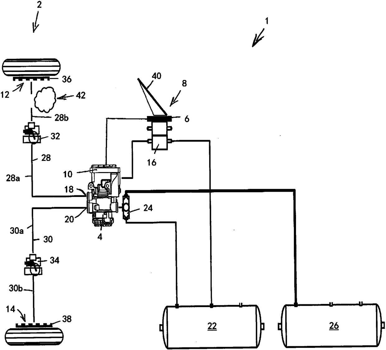
[0045] figure 1 A partial view of a schematic connection diagram of a preferred embodiment of an electropneumatic brake system 1 for a commercial vehicle is shown in . Only the components and assemblies associated with the front axle 2 are shown here. The electropneumatic brake system 1 is in particular an electronically regulated braking system (EBS) with brake pressure regulation on all braked axles or wheels. The electropneumatic brake system 1 has an ABS system on all braked wheels.

[0046] For example, a single-channel pressure regulation module 4 is assigned to the front axle 2 , which is based on an electronic controller (not shown in detail here) fed to the pressure regulation module 4 by the electrical channel 6 of the foot brake module 8 . 10 to generate brake pressure for eg the first right brake cylinder 12 and eg for the second left brake cylinder 14 . The two brake cylinders 12 , 14 are not shown in detail here.

[0047] Electronic controller 10, combination...


PUM


Abstract

The invention relates to a method for detection and reduction of the negative consequences of a leak in a pneumatic brake line (28, 30) of an electropneumatic brake device (1) having an ABS control, which has ABS pressure control valves (32, 34) in the brake lines (28, 30) and a pressure sensor in a pressure control module (4). According to the invention, the leak is detected by measuring the actual brake pressure by means of the pressure sensor and switching the ABS pressure control valves (32, 34), and the consequences of said leak are reduced by blocking the brake line affected by the leak(28, 30) by means of the associated ABS pressure control valve (32, 34).

Description

technical field [0001] The invention relates to a method for detecting and compensating leaks in an electropneumatic brake system with an ABS system according to the preamble of claim 1 and to a vehicle according to the preamble of claim 10 Electro-pneumatic brakes with ABS system with algorithms implemented in the electronic controller for detection and compensation of leaks. Background technique [0002] The described brake system with ABS system usually has a single-channel pressure regulation module with integrated electronic controller, a first brake cylinder (for example for the right side of the vehicle) and a first brake cylinder (for example for the left side of the vehicle) on the front axle a) a second brake cylinder and a first pneumatic brake circuit and a second pneumatic brake circuit, wherein the first pneumatic brake circuit is arranged between the first outlet of the channel of the pressure regulating module and the first pneumatic brake cylinder , and the...

Claims


Application Information

Patent Timeline
Patent Type & Authority Applications(China)
IPC IPC(8): B60T17/22B60T8/88B60T13/66
CPCB60T8/327B60T8/94B60T13/66B60T13/662B60T17/18B60T17/221B60T17/226B60T2270/206B60T2270/40B60T2270/403B60T2270/413B60T2270/88
Inventor M·诺勒
Owner KNORR-BREMSE SYST FUER NUTZFAHRZEUGE GMBH
Why Eureka
Try Eureka