
Patsnap Eureka
For R&D, Patsnap Eureka makes reading and utilizing patents & technical documents easy.
Patsnap Eureka AIR
Designed for self-driven R&D workflows. Generate viable solutions, solve complex R&D challenges, empower your innovation with AI.

Patsnap Eureka Materials
Designed for material experts only. Revolutionize your material R&D, from search, analyze, to developing new materials.

TechResearch
Generate reliable direction feasibility study reports for your R&D in just a few steps.

TechSeek
Discover and master advanced knowledge NOW. Basics, ideas, possibilities, all at once.

TechMind
As an expert in R&D Theories, TechMind can generates customized viable solutions instantly.

TechRisk
Analyze your overall solution with one click, know your potential R&D risks in advance.

TechMonitor
Get weekly tech updates, stay abreast of the latest tech innovations and key insights.
Radar sensor for driver assistance systems in motor vehicles
A technology of radar sensor and driver assistance, applied in the field of radar sensor of driver assistance system, can solve the problem of limiting the acceptability of driver assistance system
- Summary
- Abstract
- Description
- Claims
- Application Information
AI Technical Summary
Problems solved by technology
Method used
Image

Examples
Embodiment Construction
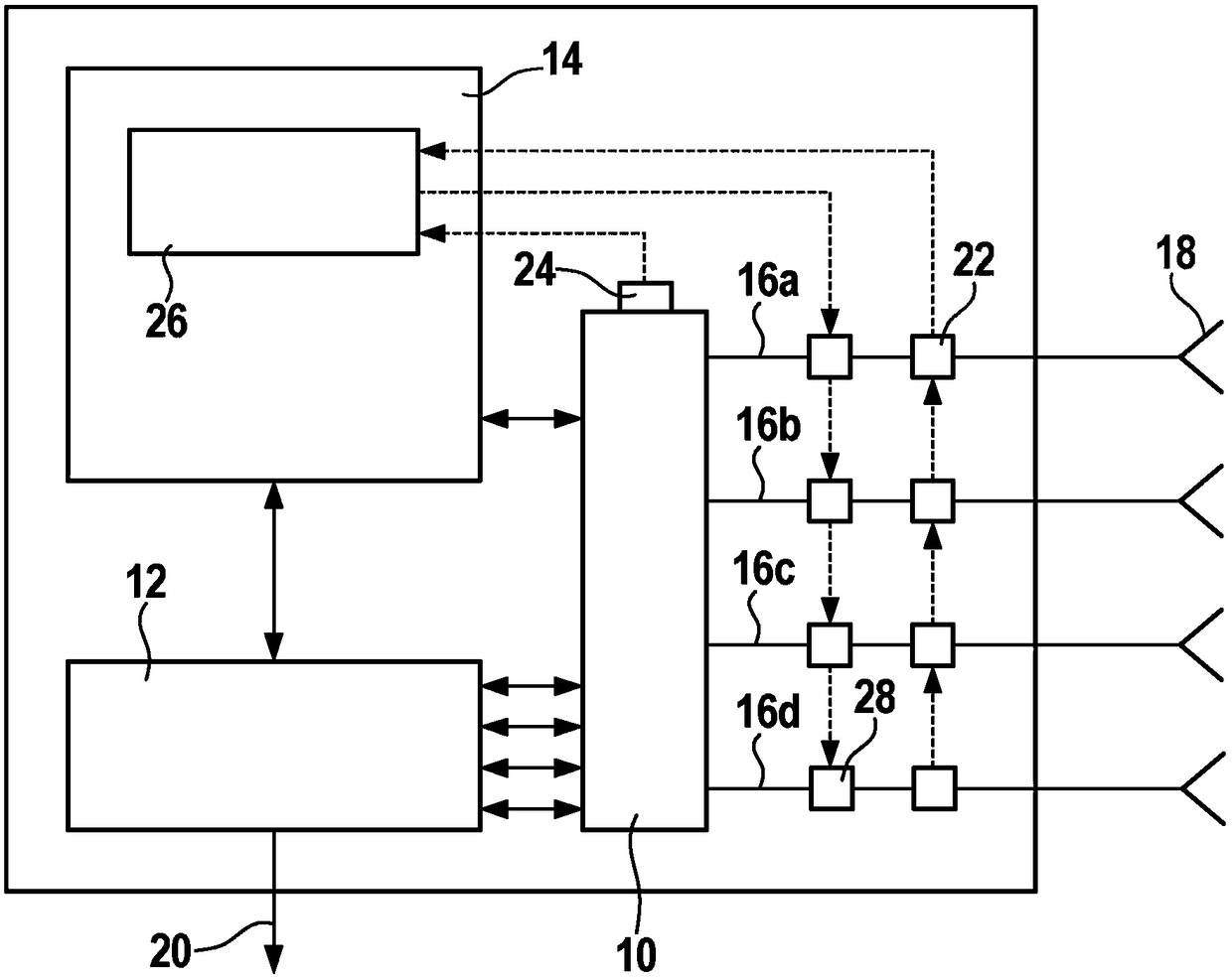
[0022] figure 1 The radar sensor shown in has a transmitter and receiver unit 10 , an evaluation unit 12 and a control unit 14 , which controls the various workflows in the transmitter and receiver unit 10 and in the evaluation unit 12 .
[0023] The transmitting and receiving device 10 is used to transmit and receive radar signals on four parallel transmitting and receiving channels 16a to 16d. Each channel is assigned an antenna 18 which is used both for transmitting radar signals and for receiving radar echoes.
[0024] As an example, it is assumed that the radar sensor described here is a so-called FMCW (Frequency Modulated Continuous Wave) radar. The transmitting and receiving device 10 feeds each of the transmitting and receiving channels 16 a to 16 d a radar signal whose frequency is ramp-modulated such that the signal consists of a series of successive linear frequency ramps. In each channel, the received radar echoes are then mixed with a part of the associated tran...
PUM
 Abstract
Description
Claims
Application Information
 - R&D Engineer
- R&D Manager
- IP Professional
- Industry Leading Data Capabilities
- Powerful AI technology
- Patent DNA Extraction
Browse by: Latest US Patents, China's latest patents, Technical Efficacy Thesaurus, Application Domain, Technology Topic, Popular Technical Reports.
© 2024 PatSnap. All rights reserved.Legal|Privacy policy|Modern Slavery Act Transparency Statement|Sitemap|About US| Contact US: help@patsnap.com