A positioning method for bogie bearing spring
A positioning method and bogie technology, applied in manufacturing tools, hand-held tools, etc., can solve the problems of inaccurate positioning of load-bearing springs, slow positioning speed, etc., and achieve the effects of accurate and fast positioning, fast receiving speed, and simple procedures
- Summary
- Abstract
- Description
- Claims
- Application Information
AI Technical Summary
Problems solved by technology
Method used
Image

Examples
Embodiment 1
[0051] The present invention includes the following steps:
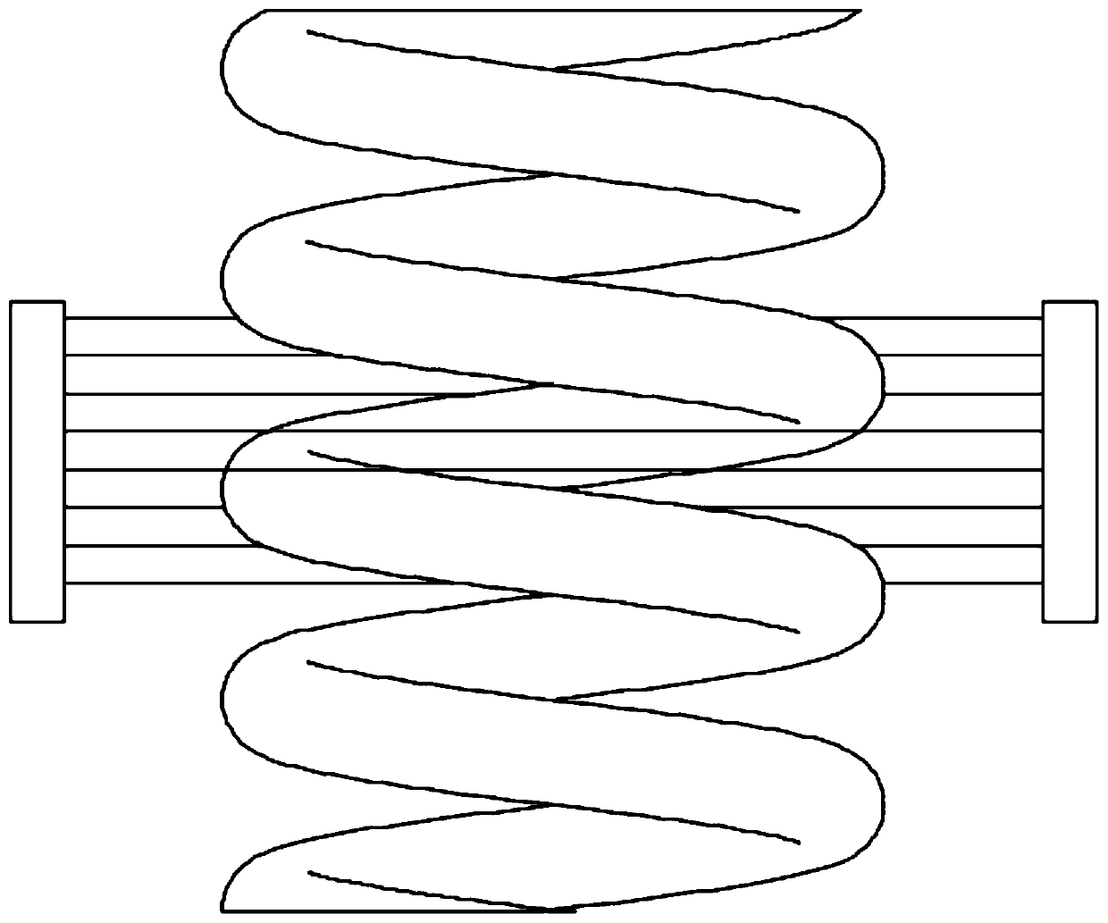
[0052] S1. On the left and right sides of the load-bearing spring, there are multiple groups of through-beam fiber optic sensor receiving ends and through-beam fiber optic sensor transmitting ends; multiple groups of through-beam fiber optic sensors are fixed on the fixture as a whole, the fixture A manipulator is connected by a flange, and a T-hook head for picking and placing the load-bearing spring is also provided on the fixture. The vertical distance between the center of the T-hook head and the through-beam optical fiber sensor remains unchanged; adjacent through-beam types The spacing of the fiber optic sensors is the same.
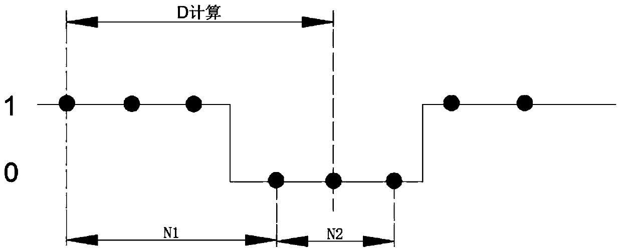
[0053] S2. The output switch signal of the through-beam optical fiber sensor is "True" and "False". During the positioning process, the output is False when the receiving end and the transmitting end are set to be unobstructed, otherwise it is True, and the corresponding I / 0 signal is : "1" m...
Embodiment 2
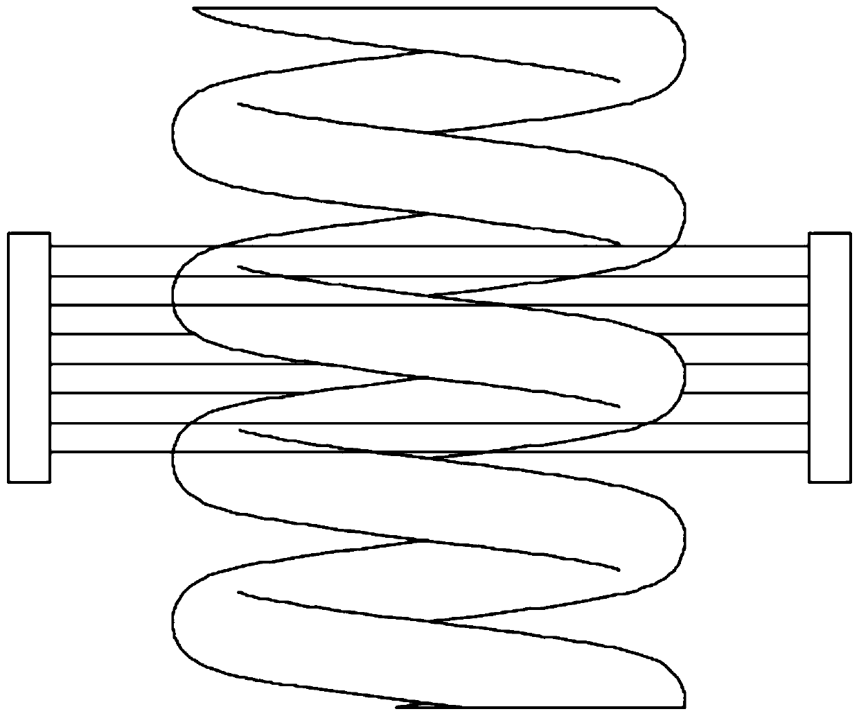
[0059] By limiting the distance W between the uppermost through-beam fiber optic sensor and the lowermost through-beam fiber optic sensor:
[0060] max{D spring , L Spring clearance } spring +2·L Spring clearance , L Spring clearance +2·D spring }, where D spring Indicates the wire diameter of the loaded spring. It is ensured that the relative positional relationship between the through-beam fiber optic sensor and the spring will only appear as shown below. figure 1 With attached figure 2 Of the two cases, attached figure 1 With attached figure 2 The corresponding I / 0 are as attached image 3 With attached Figure 4 Shown. Attached image 3 With attached Figure 4 The "1" in "True" means that the transmitting end and the output end are blocked, and there is a load-bearing spring between the pair of through-beam optical fiber sensors; "0" means "False" that the transmitting end and the output end are not blocked. There is no spring blocking between the through-beam fiber...
PUM
 Abstract
Description
Claims
Application Information
 - R&D Engineer
- R&D Manager
- IP Professional
- Industry Leading Data Capabilities
- Powerful AI technology
- Patent DNA Extraction
Browse by: Latest US Patents, China's latest patents, Technical Efficacy Thesaurus, Application Domain, Technology Topic.
© 2024 PatSnap. All rights reserved.Legal|Privacy policy|Modern Slavery Act Transparency Statement|Sitemap