
Combined-type air inlet and exhaust valve

A composite technology of intake and exhaust valves, applied in the direction of valve details, safety valves, balance valves, etc., can solve the problems of not meeting the requirements of small-diameter pipelines and large volume of intake and exhaust valves, and achieve compact structure and small volume , Alleviate bulky effect

Pending Publication Date: 2018-10-02
TIANJIN GUOWEI FEEDING & DRAINAGE EQUIP MENT MFG
View PDF0 Cites 5 Cited by
  • Summary
  • Abstract
  • Description
  • Claims
  • Application Information

AI Technical Summary

Problems solved by technology

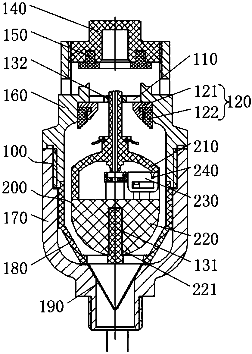
[0006] The purpose of the present invention is to provide a composite intake and exhaust valve to alleviate the large volume of the intake and exhaust valve assembled by the floating ball type exhaust valve and the buoy type micro exhaust valve in the prior art. Small diameter pipe use requirements and other issues

Method used


Image

  • Combined-type air inlet and exhaust valve
  • Combined-type air inlet and exhaust valve
  • Combined-type air inlet and exhaust valve

Examples


Embodiment Construction

[0059] The technical solutions of the present invention will be clearly and completely described below in conjunction with the accompanying drawings. Apparently, the described embodiments are some of the embodiments of the present invention, but not all of them. Based on the embodiments of the present invention, all other embodiments obtained by persons of ordinary skill in the art without making creative efforts belong to the protection scope of the present invention.

[0060] In the description of the present invention, it should be noted that the terms "center", "upper", "lower", "left", "right", "vertical", "horizontal", "inner", "outer" etc. The indicated orientation or positional relationship is based on the orientation or positional relationship shown in the drawings, and is only for the convenience of describing the present invention and simplifying the description, rather than indicating or implying that the referred device or element must have a specific orientation, ...


PUM


Abstract

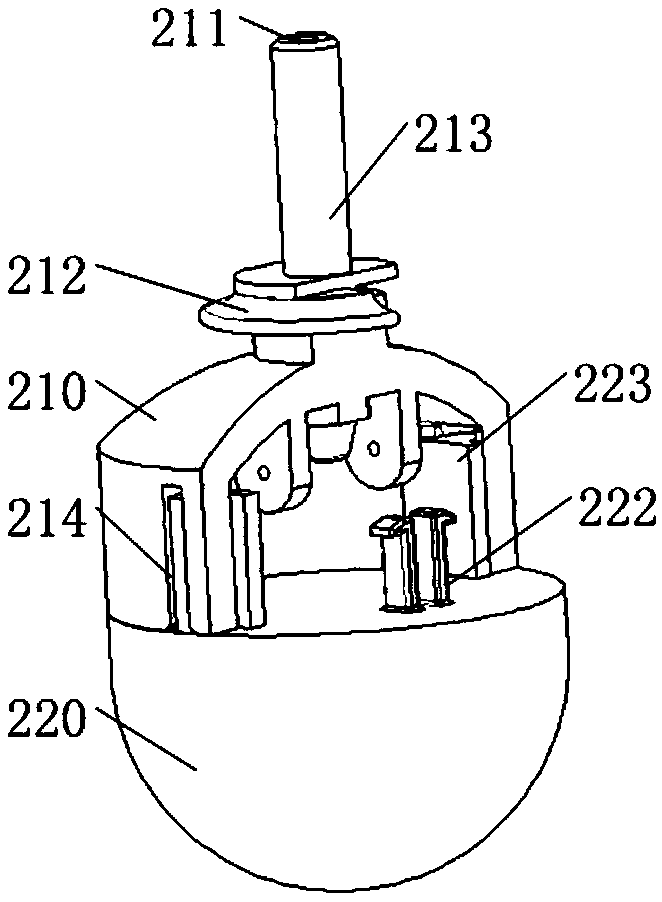
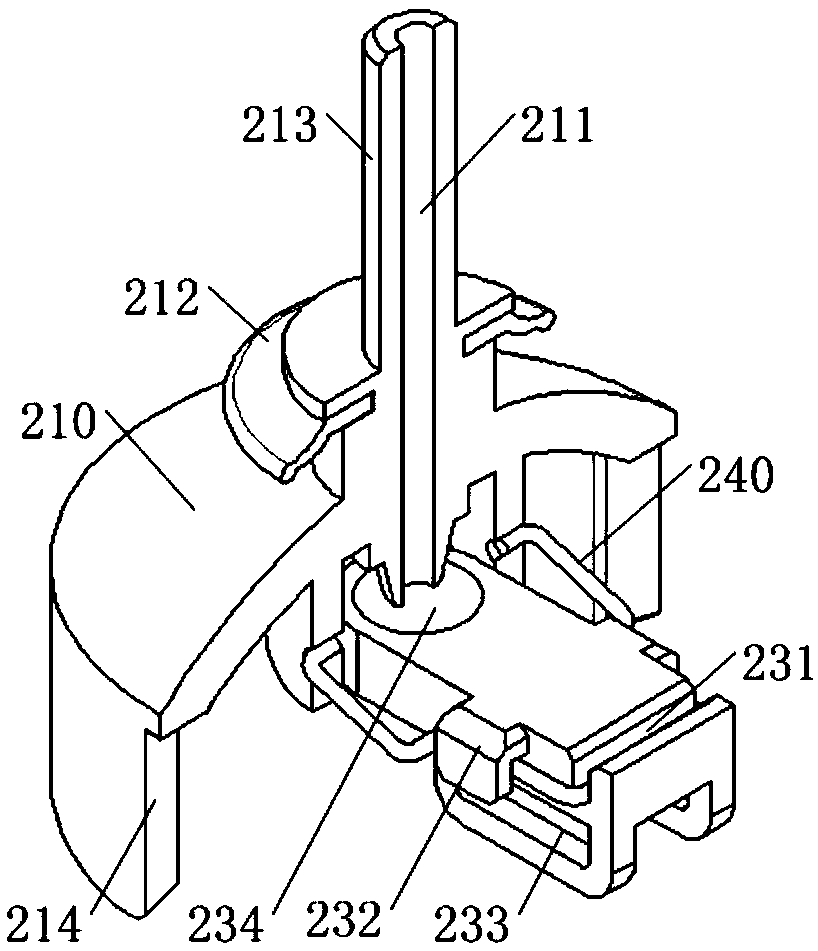
The invention provides a combined-type air inlet and exhaust valve and relates to the technical field of valves. The combined-type air inlet and exhaust valve comprises a valve body and further comprises an upper valve element and a lower valve element which are arranged in the valve body. A first vent hole is formed in the valve body and can be opened or closed by the upper valve element; the upper valve element and the lower valve element are slidably connected so that the upper valve element and the lower valve element can be buckled or separated mutually; a valve plate is arranged betweenthe upper valve element and the lower valve element, connected with the upper valve element through an elastic piece and connected with the lower valve element; and when the lower valve element and the upper valve element are separated, a second vent hole in the upper valve element is opened by the valve plate, and when the lower valve element and the upper valve element are buckled, the second vent hole can be closed by the valve plate. The problem that in the prior art, an air inlet and exhaust valve formed by assembling a floating-ball-type mass air exhaust valve and a float-type trace airexhaust valve is large in size, and consequently the using requirements of a small-diameter pipeline cannot be met is relieved.

Description

technical field [0001] The invention relates to the technical field of valves, in particular to a composite intake and exhaust valve. Background technique [0002] Under normal circumstances, there will be some air dissolved in the water in the pipeline, and in the process of water flow, the air will gradually separate from the water and gradually gather together to form large air bubbles. Therefore, it is necessary to install an exhaust valve on the pipeline for easy exhaust. [0003] The traditional composite intake and exhaust valves are generally assembled by a large number of float-type exhaust valves and float-type micro-exhaust valves. They are bulky and their nominal size is generally greater than DN50. Therefore, they cannot meet the requirements of small-diameter pipelines. [0004] Based on the above problems, it is particularly important to propose a composite intake and exhaust valve that integrates the functions of a large number of exhaust valves and a small ...

Claims


Application Information

Patent Timeline
IPC IPC(8): F16K31/20F16K17/12
CPCF16K17/12F16K31/20
Inventor 刘永张志鹏龚高石
Owner TIANJIN GUOWEI FEEDING & DRAINAGE EQUIP MENT MFG
Learn More