Dual sealing device for high-pressure pipeline in automobile engine
An automobile engine, medium and high pressure technology, which is applied in the direction of mechanical equipment, pipes/pipe joints/fittings, flange connections, etc. It can solve problems such as leakage at the interface and affect the service life of the workpiece, so as to prevent leakage risks and strong self-adaptive ability , The effect of reducing the risk of leakage
- Summary
- Abstract
- Description
- Claims
- Application Information
AI Technical Summary
Problems solved by technology
Method used
Image

Examples
Embodiment 1
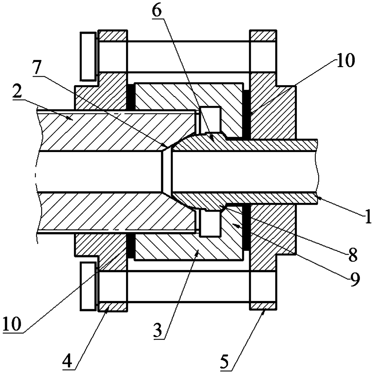
[0022] Such as figure 1 As shown, a double sealing device for high-pressure pipelines in automobile engines includes a pier type adapter device 1, a double threaded joint 2, a lock nut 3, a flange A4 and a flange B5, wherein the The pier head type adapter device 1 includes a pipe body with a hollow structure, one end of the pipe body has a pier head 6 structure, and the other end communicates with the high-pressure pipeline, and the tail end of the pier head 6 has a spherical step 8; The double-threaded joint 2 has a hollow structure, and one end face is provided with a concave hole 7 that matches the pier head 6 of the pier head type adapter device 1. There is a gap between the concave hole 7 and the pier head 6 that can realize the relative rotation of the two. The mating surface of this end is fitted with a flange A4 on the external thread; the lock nut 3 is coaxially set on the pipe body of the pier type adapter device 1, and the internal thread of the lock nut 3 is connec...
Embodiment 2
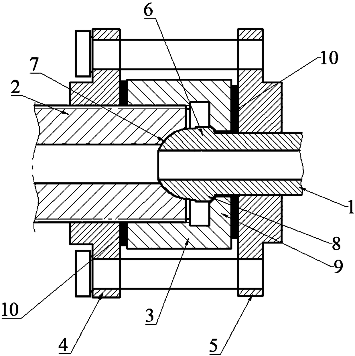
[0029] Such as figure 2 , a double sealing device for high-pressure pipelines in automobile engines, including a pier type adapter device 1, a double threaded joint 2, a lock nut 3, a flange A4 and a flange B5, wherein the pier The head type adapter device 1 includes a pipe body with a hollow structure, one end of the pipe body has a pier head 6 structure, and the other end communicates with the high-pressure pipeline, and the tail end of the pier head 6 has a spherical step 8; The threaded joint 2 has a hollow structure, and one end surface is provided with a concave hole 7 that cooperates with the pier head 6 of the pier head type adapter device 1. There is a cooperation between the concave hole 7 and the pier head 6 that can realize the relative rotation of the two. On the surface, a flange A4 is set on the external thread of this end; the lock nut 3 is coaxially set on the pipe body of the pier type adapter device 1, and the internal thread of the lock nut 3 is matched wi...
PUM
 Abstract
Description
Claims
Application Information
PatSnap Eureka turns technology decisions into work you can execute. Powered by our Innovation Knowledge Graph, it runs expert workflows across engineering, life sciences, materials and intellectual property. Get your review-ready output in minutes.


