Method and system for fitting cooling curve

A technology of cooling curves and curves, which is applied in the field of thermal performance testing of electronic devices, can solve problems such as system errors and random noise errors, and achieve the effects of noise reduction, high fitting degree, and simple calculation methods

Active Publication Date: 2018-10-02
SHANGHAI UNIV
View PDF6 Cites 0 Cited by
  • Summary
  • Abstract
  • Description
  • Claims
  • Application Information

AI Technical Summary

Problems solved by technology

[0010] In view of the above-mentioned shortcomings of the prior art, the purpose of the present invention is to provide a cooling curve fitting method and system, which is used to solve the problem of how to simply and effectively reduce the systematic errors and problems in the cooling curve of the acquisition test in the prior art. The problem with random noise errors

Method used


Image

  • Method and system for fitting cooling curve
  • Method and system for fitting cooling curve
  • Method and system for fitting cooling curve

Examples


Embodiment 1

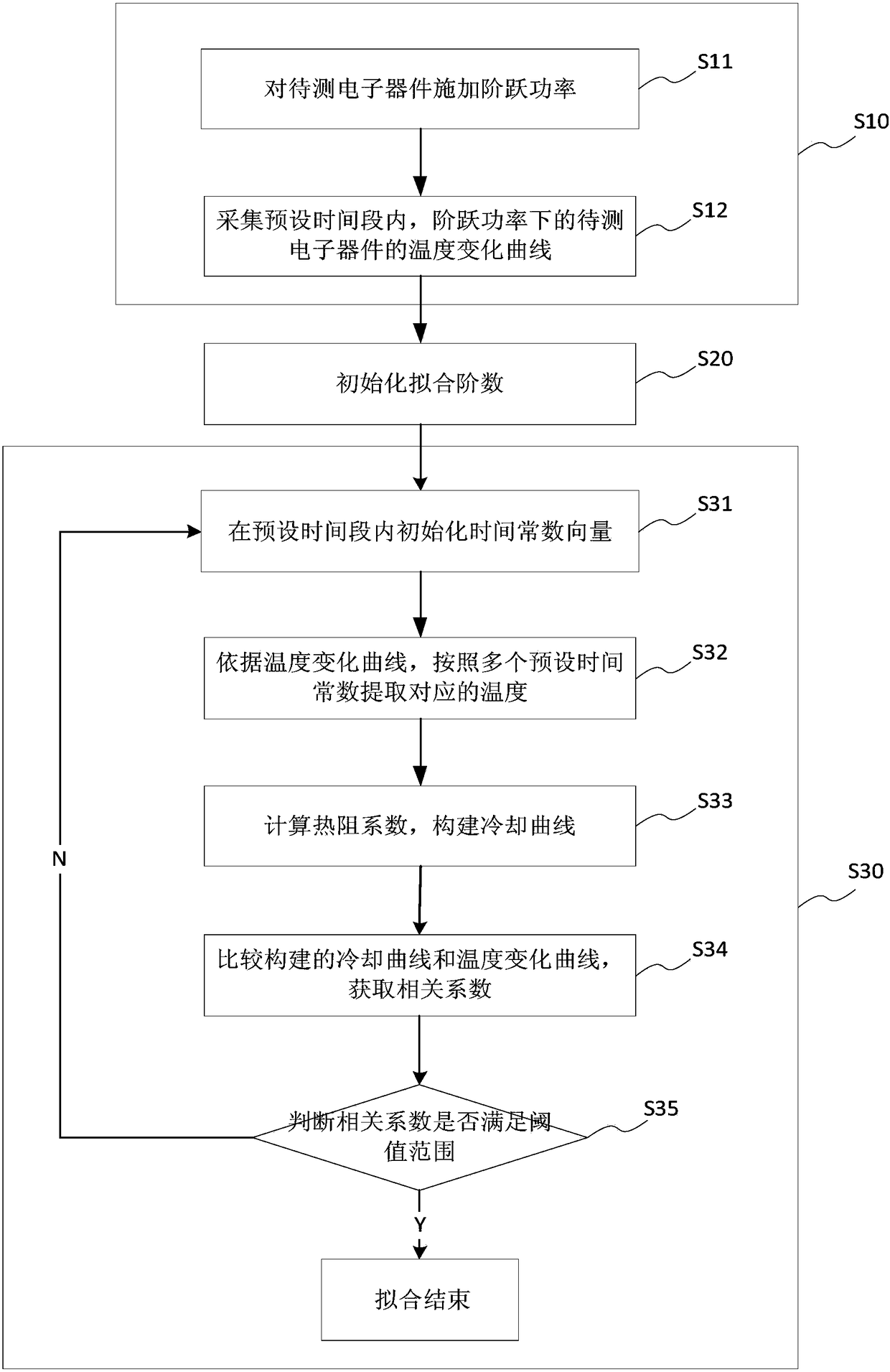
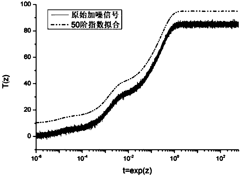
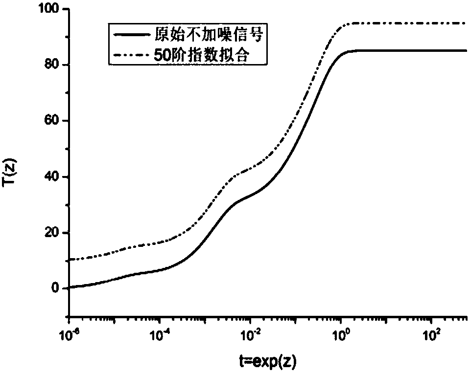
[0059] This embodiment discloses a cooling curve fitting method for transient heat test data, which is to use formula (5) to exponentially fit the actually measured cooling curve.

[0060] Such as figure 1 Shown, the cooling method of the cooling curve of the present embodiment comprises:

[0061] Step S10, collecting a temperature change curve of the temperature of the electronic device under test over time within a preset time;

[0062] This embodiment adopts the transient thermal analysis method, then, before collecting the temperature change curve of the electronic device to be tested, it is necessary to apply a step heating power to the electronic device. Therefore, step S10 specifically includes:

[0063] Step S11, applying step power to the electronic device under test;

[0064] Step S12, collecting the temperature change curve of the electronic device under test under step power within a preset time period.

[0065] Wherein, the preset time period is preset accordi...

Embodiment 2

[0090] This embodiment discloses a cooling curve fitting system for transient thermal test data, which uses formula (5) to exponentially fit the actually measured cooling curve.

[0091] Such as Figure 4 As shown, the fitting system of the cooling curve disclosed in this embodiment includes:

[0092] The collection module 410 is used to collect the temperature change curve of the temperature of the electronic device under test over time within a preset time period;

[0093] Wherein, the collection module 410 includes a power application sub-module 411 and a collection sub-module 412 . The power applying sub-module 411 is used to apply step power to the electronic device under test; the collection sub-module 412 is used to collect the temperature change curve of the electronic device under test under step power within a preset time period.

[0094]The initialization module 420 is used to initialize the fitting order and the time constant vector; wherein, the time constant ve...


PUM


Abstract

The invention provides a method and system for fitting a cooling curve. The method and system are applied to thermal performance testing of electronic devices. The method includes the steps that a temperature change curve of the electronic devices to be tested within a preset time period is collected, and a fitting order is initialized; according to the fitting order, the cooling curve is fitted;within a preset time period, a time constant vector is initialized; according to the temperature change curve, corresponding temperatures are extracted according to multiple preset time constants; according to the preset time constants and correspondingly extracted temperature calculation thermal resistance coefficients, the cooling curve is constructed; the constructed cooling curve is compared with the temperature change curve to obtain related coefficients; the related coefficients are judged, wherein fitting is completed for the cooling curve when the related coefficients are in a threshold value range, and when the related coefficients are not in the threshold value range, the fitting order is increased, and the cooling curve is fitted again. The method for fitting the cooling curve is simple and high in fitting degree, and reduces influences of noise on fitting of the cooling curve to the maximum degree.

Description

technical field [0001] The invention relates to the field of thermal performance testing of electronic devices, in particular to a fitting method and system for cooling curves of electronic devices. Background technique [0002] With the continuous progress and development of the information society, the level of electronic technology needs to be continuously improved to meet the needs of the society. Miniaturization and full-featured are the development directions of electronic devices, and all kinds of electronic devices face common fatal problems. The problem is heat dissipation. Thermal resistance is an important index to measure the thermal performance of a device, so the thermal resistance of a device is usually used to judge the thermal performance of an electronic device. [0003] Currently, thermal resistance testing methods include: [0004] 1) Infrared thermal imaging method, which mainly analyzes the temperature field distribution of semiconductors to obtain th...

Claims


Application Information

Patent Timeline
Patent Type & Authority Applications(China)
IPC IPC(8): G01N25/20
CPCG01N25/20
Inventor 杨连乔刘亚男徐小雪张建华
Owner SHANGHAI UNIV
Why Eureka
Try Eureka