
Detection method of semiconductor laser degradation mechanism

A detection method and laser technology, applied in the direction of single semiconductor device testing, etc., can solve the problems of high economic cost, low efficiency, long time consumption, etc., and achieve the effect of prolonging the working life.

Inactive Publication Date: 2016-07-27
杭州增益光电科技有限公司
View PDF5 Cites 10 Cited by
  • Summary
  • Abstract
  • Description
  • Claims
  • Application Information

AI Technical Summary

Problems solved by technology

Since the applied lasers are all packaged devices, it takes a long time and low efficiency to use conventional analysis methods, and requires a variety of equipment to be used together, which is also expensive economically.

Method used


Image

  • Detection method of semiconductor laser degradation mechanism
  • Detection method of semiconductor laser degradation mechanism
  • Detection method of semiconductor laser degradation mechanism

Examples


Embodiment 1

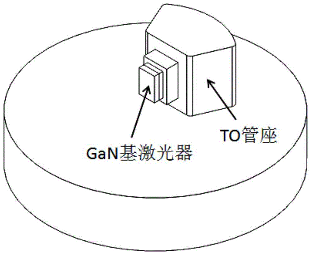
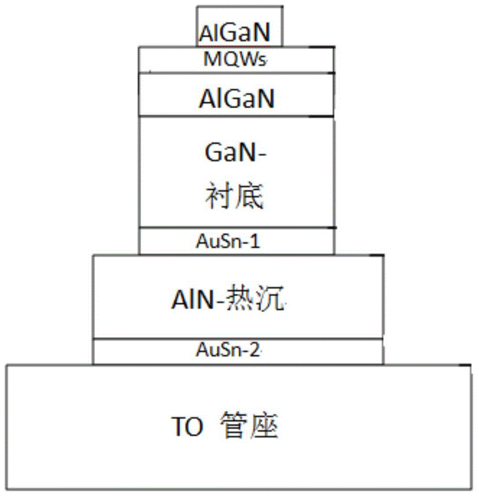
[0043] Embodiment 1: This embodiment takes a GaN-based semiconductor laser as an example (see Figure 1a Schematic diagram of the structure of GaN-based lasers packaged in TO, Figure 1b It is a schematic diagram of a GaN-based laser including a chip structure), this embodiment uses the forward voltage method to measure the relationship of the voltage of the semiconductor laser with time. According to the relationship between the voltage and temperature of the GaN-based semiconductor laser, the measured voltage-time relationship is converted into a temperature-time relationship.

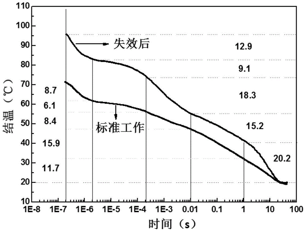
[0044] The transient cooling curves of the standard working GaN-based semiconductor laser and the failed GaN-based semiconductor laser are respectively measured according to the following methods.

[0045]The semiconductor laser is heated under the operating current for 10 minutes, and when the semiconductor laser reaches a thermally stable state, the working current is turned off and the voltage of...

Embodiment 2

[0047] Embodiment 2: This embodiment takes a GaN-based semiconductor laser as an example. In this embodiment, a forward voltage method is used to measure the relationship of the voltage of the semiconductor laser with time. According to the relationship between the voltage and temperature of the GaN-based semiconductor laser, the measured voltage-time relationship is converted into a temperature-time relationship.

[0048] The transient cooling curves of the standard working GaN-based semiconductor laser and the failed GaN-based semiconductor laser are respectively measured according to the following methods.

[0049] Heat the standard working semiconductor laser under the working current for 10 minutes until the semiconductor laser reaches thermal stability. Turn off the high working current and measure the voltage of the GaN-based semiconductor laser as a function of time at a small current of 1mA; then convert the voltage-time curve into a temperature- Time curve; draw the...


PUM


Abstract

The present invention discloses a detection method of a semiconductor laser degradation mechanism. The method comprises the steps of measuring the transient cooling curve of a failed semiconductor laser and the transient cooling curve of a normally working semiconductor laser in a same condition, comparing the two transient cooling curves, and obtaining the degradation mechanism of the failed semiconductor laser. According to the method, the transient heat transfer characteristics of the semiconductor laser is utilized, the transient cooling curve of the laser is obtained through a forward voltage junction temperature measurement method or other methods, then the degradation position of the laser is found through comparing the difference between the transient cooling curve of the failed laser and the transient cooling curve of the normally working laser, the possible failure mechanism of the laser is preliminarily determined according to the magnitude of change, thus the failure reason of the laser is rapidly determined and a solution is rapidly found, and finally the service life of the laser is prolonged.

Description

technical field [0001] The invention belongs to the technical field of reliability testing of semiconductor devices, and in particular relates to a detection method for characterizing the degradation mechanism of semiconductor lasers by utilizing the transient heat transfer principle of semiconductor lasers. Background technique [0002] As a new type of laser light source, semiconductor lasers have the advantages of high photoelectric conversion efficiency, small size, easy integration, and simple driving requirements, and because the wavelength of semiconductor lasers covers the entire wavelength range from ultraviolet to infrared, it has an extremely wide range of applications. Application prospect. With the continuous improvement of the manufacturing process of semiconductor lasers and the continuous improvement of manufacturing methods, the structure of semiconductor lasers is becoming more and more perfect, and the performance of lasers is more excellent. However, the...

Claims


Application Information

Patent Timeline
Patent Type & Authority Applications(China)
IPC IPC(8): G01R31/26
Inventor 温鹏雁李德尧张书明刘建平张立群杨辉
Owner 杭州增益光电科技有限公司
Learn More